
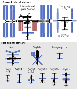
Orbital platforms
Def. a "manned [crewed] artificial satellite designed for long-term habitation, research, etc."[1] is called a space station.
Def. "a space station, generally constructed for one purpose, that orbits a celestial body such as a planet, asteroid, or star"[2] is called an orbital platform.
Apollo-Soyuz
[edit | edit source]


An artist's concept illustrates an Apollo-type spacecraft (on left) about to dock with a Soviet Soyuz-type spacecraft. A recent agreement between the United States and the Union of Soviet Socialist Republics provides for the docking in space of the Soyuz and Apollo-type spacecraft in Earth orbit in 1975. The joint venture is called the Apollo-Soyuz Test Project.
The three American astronauts, Thomas P. Stafford, Vance D. Brand, and Deke Slayton, and two Soviet cosmonauts, Alexei Leonov and Valeri Kubasov, performed both joint and separate scientific experiments, including an arranged eclipse of the Sun by the Apollo module to allow instruments on the Soyuz to take photographs of the solar corona.
The photo on the left depicts the liftoff of the Saturn IB launch vehicle (SA-210), for the Apollo/Soyuz Test Project (ASTP) mission, from the Launch Complex 39B, Kennedy Space Center. The Apollo-Soyuz Test Project (ASTP) was the first international docking of the U.S.'s Apollo spacecraft and the U.S.S.R.'s Soyuz spacecraft in space. The objective of the ASTP mission was to provide the basis for a standardized international system for docking of manned spacecraft. The Soyuz spacecraft, with Cosmonauts Alexei Leonov and Valeri Kubasov aboard, was launched from the Baikonur Cosmodrome near Tyuratam in the Kazakh, Soviet Socialist Republic, at 8:20 a.m. (EDT) on July 15, 1975. The Apollo spacecraft, with Astronauts Thomas Stafford, Vance Brand, and Donald Slayton aboard, was launched from Launch Complex 39B, Kennedy Space Center, Florida, at 3:50 p.m. (EDT) on July 15, 1975. The Primary objectives of the ASTP were achieved. They performed spacecraft rendezvous, docking and undocking, conducted intervehicular crew transfer, and demonstrated the interaction of U.S. and U.S.S.R. control centers and spacecraft crews. The mission marked the last use of a Saturn launch vehicle. The Marshall Space Flight Center was responsible for development and sustaining engineering of the Saturn IB launch vehicle during the mission.
This scene (second image down on the right) was photographed with a handheld 70 mm camera from a rendezvous window of the American Apollo spacecraft in Earth orbit during the Apollo-Soyuz Test Project (ASTP) mission. It shows the Soviet Soyuz spacecraft contrasted against a black-sky background with the Earth's horizon below. The American Docking Mechanism (DM) is visible at the top of the picture.
International Space Station (Unity-Zarya-Zvezda configuration)
[edit | edit source]-
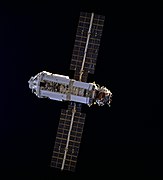
 ISS Zvezda service module with docked Progress M1-3 spacecraft. Credit: NASA.{{free media}}
 -
 Zarya is seen by Space Shuttle Endeavour during STS-88 in December 1998. Credit: NASA STS-93 crew.{{free media}}
 -
 ISS Unity module (NASA) is photographed by STS-88 mission in December 1998. Credit: NASA STS-93 crew.{{free media}}


.jpg)
At top center is the Unity-Zarya-Zvezda configuration of the ISS on 18 September 2000 outfitted for the first resident crew.
International Space Station (New solar panels configuration)
[edit | edit source]
This picture is one of a series of 70mm frames exposed of the International Space Station (ISS) following undocking at 1:13 p.m. (CST), December 9, 2000. This series of images, as well as video and digital still imagery taken at the same time, represent the first imagery of the entire station with its new solar array panels deployed. Before separation, the shuttle and space station had been docked to one another for 6 days, 23 hours and 13 minutes. Endeavour moved downward from the space station, then began a tail-first circle at a distance of about 500 feet. The maneuver, with pilot Michael J. Bloomfield at the controls, took about an hour. While Endeavour flew that circle, the two spacecraft, moving at five miles a second, navigated about two-thirds of the way around the Earth. Undocking took place 235 statute miles above the border of Kazakhstan and China. When Endeavour made its final separation burn, the orbiter and the space station were near the northeastern coast of South America.
International Space Station (Destiny module configuration)
[edit | edit source]

The image shows the Progress M1-3 module replaced by the Destiny module.
International Space Station (Backone configuration)
[edit | edit source]
STS-108 (STS-107 of the sequence of flights) was the 12th shuttle flight to visit the International Space Station and the first since the installation of the Russian airlock called Pirs on the station.
STS-110 (STS-109) was a Space Shuttle mission to the International Space Station (ISS) on 8–19 April 2002 flown by Space Shuttle Atlantis. The main purpose was to install the S0 Truss segment, which forms the backbone of the truss structure on the station.
The main purpose of STS-110 was to attach the stainless steel S0 Truss segment to the International Space Station (ISS) to the Destiny Laboratory Module. It forms the backbone of the station to which the S1 and P1 truss segments were attached (on the following missions STS-112 and STS-113, respectively).
STS-112 (STS-111) (ISS assembly flight 9A) was an 11-day Space Shuttle mission to the International Space Station (ISS) flown by Space Shuttle Atlantis.[3] Space Shuttle Atlantis was launched on 7 October 2002 at 19:45 UTC from the Kennedy Space Center's launch pad 39B to deliver the 28,000 pound Starboard 1 (S1) truss segment to the Space Station.[4]
During the 14-day mission in late 2002, Endeavour and its crew extended the ISS backbone with the P1 truss. STS-113 was an Assembly Mission (11A) to the International Space Station, delivering the P1 Truss segment, which provides structural support for the Space Station radiators.
International Space Station
[edit | edit source]


On the right is the International Space Station configuration 26 November 2021. The second image on the right is after the undocking of STS-134 Space Shuttle.
The Space Shuttle Endeavor crew captured this shot [on the left] of the International Space Station (ISS) against the backdrop of Planet Earth.
"Since 2001, NASA and its partners have operated a series of flight experiments called Materials International Space Station Experiment, or MISSE [on the second right]. The objective of MISSE is to test the stability and durability of materials and devices in the space environment."[5]
The Alpha Magnetic Spectrometer on the second left is designed to search for various types of unusual matter by measuring cosmic rays.
The Extreme Universe Space Observatory (EUSO) [on the third right] is the first Space mission concept devoted to the investigation of cosmic rays and neutrinos of extreme energy (E > 5×10¹⁹
eV). Using the Earth's atmosphere as a giant detector, the detection is performed by looking at the streak of fluorescence produced when such a particle interacts with the Earth's atmosphere.
The Space Environment Data Acquisition equipment-Attached Payload (SEDA-AP) aboard the Kibo (International Space Station module) measures neutrons, plasma, heavy ions, and high-energy light particles in ISS orbit.
On the lower right is a Bonner Ball Neutron Detector "BBND ... determined that galactic cosmic rays were the major cause of secondary neutrons measured inside ISS. The neutron energy spectrum was measured from March 23, 2001 through November 14, 2001 in the U.S. Laboratory Module of the ISS. The time frame enabled neutron measurements to be made during a time of increased solar activity (solar maximum) as well as observe the results of a solar flare on November 4, 2001."[6]
"Bonner Ball Neutron Detector (BBND) [shown with its cap off] measures neutron radiation (low-energy, uncharged particles) which can deeply penetrate the body and damage blood forming organs. Neutron radiation is estimated to be 20 percent of the total radiation on the International Space Station (ISS). This study characterizes the neutron radiation environment to develop safety measures to protect future ISS crews."[6]
Six BBND detectors were distributed around the International Space Station (ISS) to allow data collection at selected points.
"The six BBND detectors provided data indicating how much radiation was absorbed at various times, allowing a model of real-time exposure to be calculated, as opposed to earlier models of passive neutron detectors which were only capable of providing a total amount of radiation received over a span of time. Neutron radiation information obtained from the Bonner Ball Neutron Detector (BBND) can be used to develop safety measures to protect crewmembers during both long-duration missions on the ISS and during interplanetary exploration."[6]
"The Bonner Ball Neutron Detector (BBND) developed by Japan Aerospace and Exploration Agency (JAXA) was used inside the International Space Station (ISS) to measure the neutron energy spectrum. It consisted of several neutron moderators enabling the device to discriminate neutron energies up to 15 MeV (15 mega electron volts). This BBND characterized the neutron radiation on ISS during Expeditions 2 and 3."[6]
"BBND results show the overall neutron environment at the ISS orbital altitude is influenced by highly energetic galactic cosmic rays, except in the South Atlantic Anomaly (SAA) region where protons trapped in the Earth's magnetic field cause a more severe neutron environment. However, the number of particles measured per second per square cm per MeV obtained by BBND is consistently lower than that of the precursor investigations. The average dose-equivalent rate observed through the investigation was 3.9 micro Sv/hour or about 10 times the rate of radiological exposure to the average US citizen. In general, radiation damage to the human body is indicated by the amount of energy deposited in living tissue, modified by the type of radiation causing the damage; this is measured in units of Sieverts (Sv). The background radiation dose received by an average person in the United States is approximately 3.5 milliSv/year. Conversely, an exposure of 1 Sv can result in radiation poisoning and a dose of five Sv will result in death in 50 percent of exposed individuals. The average dose-equivalent rate observed through the BBND investigation is 3.9 micro Sv/hour, or about ten times the average US surface rate. The highest rate, 96 microSv/hour was observed in the SAA region."[6]
"The November 4, 2001 solar flare and the associated geomagnetic activity caused the most severe radiation environment inside the ISS during the BBND experiment. The increase of neutron dose-equivalent due to those events was evaluated to be 0.19mSv, which is less than 1 percent of the measured neutron dose-equivalent measured over the entire 8-month period."[6]
Mir
[edit | edit source]

The image on the left, includes views of Mir during Discovery's approach (010-026); the Core Assembly module (027, 051, 054, 059); the Kristall and Core Assembly modules (028-029, 063-064); the solar arrays (030, 041, 045-046); the Core Assembly module and solar arrays (031-037, 040, 043); the Kristall module and solar arrays (038-039); the Kristall module, docking unit, and solar arrays (042, 044, 047, 049); the Kristall and Core Assembly modules and solar arrays (048, 050); the Core Assembly and Kvant modules (052, 060-061); the Kvant and Progress modules (053, 062); the entire space station (055-057, 067-082); the Kristall module and docking unit (058); the Kristall and Soyuz-TM modules (065); and the Soyuz-TM, Kristall, and Core Assembly modules (066).
In the image on the right, a Progress cargo ship is attached on the left, a Soyuz manned spacecraft attached on the right. Mir is seen on the right from Space Shuttle Endeavour during STS-89 (28 January 1998).
Mir was a space station that operated in low Earth orbit from 1986 to 2001, operated by the Soviet Union and later by Russia. Mir was the first modular space station and was assembled in orbit from 1986 to 1996. It had a greater mass than any previous spacecraft. At the time it was the largest artificial satellite in orbit, succeeded by the International Space Station (ISS) after Mir's orbit decayed.
Mir was the first continuously inhabited long-term research station in orbit and held the record for the longest continuous human presence in space at 3,644 days, until it was surpassed by the ISS on 23 October 2010.[7]
The first module of the station, known as the Mir Core Module or base block, was launched in 1986 and followed by six further modules. Proton rockets were used to launch all of its components except for the Mir Docking Module, which was installed by US Space Shuttle mission STS-74 in 1995. When complete, the station consisted of seven pressurised modules and several unpressurised components. Power was provided by several photovoltaic arrays attached directly to the modules. The station was maintained at an orbit between 296 km (184 mi) and 421 km (262 mi) altitude and travelled at an average speed of 27,700 km/h (17,200 mph), completing 15.7 orbits per day.[8][9][10]
Polar Satellite 4
[edit | edit source]
PS4 has carried hosted payloads like AAM on PSLV-C8,[11] Luxspace (Rubin 9.1)/(Rubin 9.2) on PSLV-C14[12] and mRESINS on PSLV-C21.[13]
PS4 is being augmented to serve as a long duration orbital platform after completion of its primary mission. PS4 Orbital Platform (PS4-OP) will have its own power supply, telemetry package, data storage and attitude control for hosted payloads.[14][15][16]
On PSLV-C37 and PSLV-C38 campaigns,[17] as a demonstration PS4 was kept operational and monitored for over ten orbits after delivering spacecraft.[18][19][20]
PSLV-C44 was the first campaign where PS4 functioned as independent orbital platform for short duration as there was no on-board power generation capacity.[21] It carried KalamSAT-V2 as a fixed payload, a 1U cubesat by Space Kidz India based on Interorbital Systems kit.[22][23]
On PSLV-C45 campaign, the fourth stage had its own power generation capability as it was augmented with an array of fixed solar cells around PS4 propellant tank.[24] Three payloads hosted on PS4-OP were, Advanced Retarding Potential Analyzer for Ionospheric Studies (ARIS 101F) by IIST,[25] experimental Automatic identification system (AIS) payload by ISRO and AISAT by Satellize.[26] To function as orbital platform, fourth stage was put in spin-stabilized mode using its RCS thrusters.[27]
Salyut 1
[edit | edit source]
Salyut 1 (DOS-1) was the world's first space station launched into low Earth orbit by the Soviet Union on April 19, 1971. The Soyuz 11 crew achieved successful hard docking and performed experiments in Salyut 1 for 23 days.
Civilian Soviet space stations were internally referred to as DOS (the Russian acronym for "Long-duration orbital station"), although publicly, the Salyut name was used for the first six DOS stations (Mir was internally known as DOS-7).[28]
The astrophysical Orion 1 Space Observatory designed by Grigor Gurzadyan of Byurakan Observatory in Armenia, was installed in Salyut 1. Ultraviolet spectrograms of stars were obtained with the help of a mirror telescope of the Mersenne Three-mirror_anastigmat system and a spectrograph of the Wadsworth system using film sensitive to the far ultraviolet. The dispersion of the spectrograph was 32 Å/mm (3.2 nm/mm), while the resolution of the spectrograms derived was about 5 Å at 2600 Å (0.5 nm at 260 nm). Slitless spectrograms were obtained of the stars Vega and Beta Centauri between 2000 and 3800 Å (200 and 380 nm).[29] The telescope was operated by crew member Viktor Patsayev, who became the first man to operate a telescope outside of the Earth's atmosphere.[30]
Salyut 3
[edit | edit source]
Salyut 3; also known as OPS-2[31] or Almaz 2[32]) was a Soviet Union space station launched on 25 June 1974. It was the second Almaz military space station, and the first such station to be launched successfully.[32] It was included in the Salyut program to disguise its true military nature.[33] Due to the military nature of the station, the Soviet Union was reluctant to release information about its design, and about the missions relating to the station.[34]
It attained an altitude of 219 to 270 km on launch[35] and NASA reported its final orbital altitude was 268 to 272 km.[36]
The space stations funded and developed by the military, known as Almaz stations, were roughly similar in size and shape to the civilian DOS stations.[34] But the details of their design, which is attributed to Vladimir Chelomey, are considered to be significantly different from the DOS stations.[34] The first Almaz station was Salyut 2, which launched in April 1973, but failed only days after reaching orbit, and hence it was never manned.[32]
Salyut 3 consisted of an airlock chamber, a large-diameter work compartment, and a small diameter living compartment, giving a total habitable volume of 90 m³.[37] It had two solar arrays, one docking port, and two main engines, each of which could produce 400 kgf (3.9 kN) of thrust.[37] Its launch mass was 18,900 kg.[32]
The station came equipped with a shower, a standing sleeping station, as well as a foldaway bed.[32] The floor was covered with hook and loop fastener (Velcro) to assist the cosmonauts moving around the station. Some entertainment on the station included a magnetic chess set, a small library, and a cassette deck with some audio compact Cassette tapes.[37] Exercise equipment included a treadmill and Pingvin exercise suit.[37] The first water-recycling facilities were tested on the station; the system was called Priboy.[32]
The work compartment was dominated by the Agat-1 Earth-observation telescope, which had a focal length of 6.375 metres and an optical resolution better than three metres, according to post-Soviet sources;[38]. Another NASA source[32] states the focal length was 10 metres; but Portree's document preceded Siddiqi's by several years, during which time more information about the specifications was gathered. NASA historian Siddiqi has speculated that given the size of the telescope's mirror, it likely had a resolution better than one metre.[38] The telescope was used in conjunction with a wide-film camera, and was used primarily for military reconnaissance purposes.[38] The cosmonauts are said to have observed targets set out on the ground at Baikonur. Secondary objectives included study of water pollution, agricultural land, possible ore-bearing landforms, and oceanic ice formation.[32]
The Salyut 3, although called a "civilian" station, was equipped with a "self-defence" gun which had been designed for use aboard the station, and whose design is attributed to Alexander Nudelman.[31] Some accounts claim the station was equipped with a Nudelman-Rikhter "Vulkan" gun, which was a variant of the Nudelman-Rikhter NR-23 (23 mm Nudelman) aircraft cannon, or possibly a Nudelman-Rikhter NR-30 (Nudelman NR-30) 30 mm gun.[39] Later Russian sources indicate that the gun was the virtually unknown (in the West) Rikhter R-23.[40] These claims have reportedly been verified by Pavel Popovich, who had visited the station in orbit, as commander of Soyuz 14.[39] Due to potential shaking of the station, in-orbit tests of the weapon with cosmonauts in the station were ruled out.[31] The gun was fixed to the station in such a way that the only way to aim would have been to change the orientation of the entire station.[31][39] Following the last manned mission to the station, the gun was commanded by the ground to be fired; some sources say it was fired to depletion,[39] while other sources say three test firings took place during the Salyut 3 mission.[31]
Salyut 4
[edit | edit source]
Installed on the Salyut 4 were OST-1 (Orbiting Solar Telescope) 25 cm solar telescope with a focal length of 2.5m and spectrograph shortwave diffraction spectrometer for far ultraviolet emissions, designed at the Crimean Astrophysical Observatory, and two X-ray telescopes.[41][42] One of the X-ray telescopes, often called the Filin telescope, consisted of four gas flow proportional counters, three of which had a total detection surface of 450 cm2 in the energy range 2–10 keV, and one of which had an effective surface of 37 cm2 for the range 0.2 to 2 keV (32 to 320 Attojoule (aJ)). The field of view was limited by a slit collimator to 3 in × 10 in full width at half maximum. The instrumentation also included optical sensors which were mounted on the outside of the station together with the X-ray detectors, and power supply and measurement units which were inside the station. Ground-based calibration of the detectors was considered along with in-flight operation in three modes: inertial orientation, orbital orientation, and survey. Data could be collected in 4 energy channels: 2 to 3.1 keV (320 to 497 aJ), 3.1 to 5.9 keV (497 to 945 aJ), 5.9 to 9.6 keV (945 to 1,538 aJ), and 2 to 9.6 keV (320 to 1,538 aJ) in the larger detectors. The smaller detector had discriminator levels set at 0.2 keV (32 aJ), 0.55 keV (88 aJ), and 0.95 keV (152 aJ).[43]
Other instruments include a swivel chair for vestibular function tests, lower body negative pressure gear for cardiovascular studies, bicycle ergometer integrated physical trainer (electrically driven running track 1 m X .3 m with elastic cords providing 50 kg load), penguin suits and alternate athletic suit, sensors for temperature and characteristics of upper atmosphere, ITS-K infrared telescope spectrometer and ultraviolet spectrometer for study of earth's infrared radiation, multispectral earth resources camera, cosmic ray detector, embryological studies, new engineering instruments tested for orientation of station by celestial objects and in darkness and a teletypewriter.[43]
Salyut 5
[edit | edit source]
Salyut 5 carried Agat, a camera which the crews used to observe the Earth. The first manned mission, Soyuz 21, was launched from Baikonur on 6 July 1976, and docked at 13:40 UTC the next day.[44]
On 14 October 1976, Soyuz 23 was launched carrying Vyacheslav Zudov and Valery Rozhdestvensky to the space station. During approach for docking the next day, a faulty sensor incorrectly detected an unexpected lateral motion. The spacecraft's Igla automated docking system fired the spacecraft's maneuvering thrusters in an attempt to stop the non-existent motion. Although the crew was able to deactivate the Igla system, the spacecraft had expended too much fuel to reattempt the docking under manual control. Soyuz 23 returned to Earth on 16 October without completing its mission objectives.
The last mission to Salyut 5, Soyuz 24, was launched on 7 February 1977. Its crew consisted of cosmonauts Viktor Gorbatko and Yury Glazkov, who conducted repairs aboard the station and vented the air which had been reported to be contaminated. Scientific experiments were conducted, including observation of the sun. The Soyuz 24 crew departed on 25 February. The short mission was apparently related to Salyut 5 starting to run low on propellant for its main engines and attitude control system.[31]
Salyut 6
[edit | edit source]
Salyut 6 aka DOS-5, was a Soviet orbital space station, the eighth station of the Salyut programme. It was launched on 29 September 1977 by a Proton rocket. Salyut 6 was the first space station to receive large numbers of crewed and uncrewed spacecraft for human habitation, crew transfer, international participation and resupply, establishing precedents for station life and operations which were enhanced on Mir and the International Space Station.
Salyut 6 was the first "second generation" space station, representing a major breakthrough in capabilities and operational success. In addition to a new propulsion system and its primary scientific instrument—the BST-1M multispectral telescope—the station had two docking ports, allowing two craft to visit simultaneously. This feature made it possible for humans to remain aboard for several months.[45] Six long-term resident crews were supported by ten short-term visiting crews who typically arrived in newer Soyuz craft and departed in older craft, leaving the newer craft available to the resident crew as a return vehicle, thereby extending the resident crew's stay past the design life of the Soyuz. Short-term visiting crews routinely included international cosmonauts from Warsaw pact countries participating in the Soviet Union's Intercosmos programme. These cosmonauts were the first spacefarers from countries other than the Soviet Union or the United States. Salyut 6 was visited and resupplied by twelve uncrewed Progress spacecraft including Progress 1, the first instance of the series. Additionally, Salyut 6 was visited by the first instances of the new Soyuz-T spacecraft.
Salyut 7
[edit | edit source]
Salyut 7 a.k.a. DOS-6, short for Durable Orbital Station[32]) was a space station in low Earth orbit from April 1982 to February 1991.[32] It was first crewed in May 1982 with two crew via Soyuz T-5, and last visited in June 1986, by Soyuz T-15.[32] Various crew and modules were used over its lifetime, including 12 crewed and 15 uncrewed launches in total.[32] Supporting spacecraft included the Soyuz T, Progress, and TKS spacecraft.[32]
Skylab
[edit | edit source].jpg)
Skylab included an Apollo Telescope Mount, which was a multi-spectral solar observatory. Numerous scientific experiments were conducted aboard Skylab during its operational life, and crews were able to confirm the existence of coronal holes in the Sun. The Earth Resources Experiment Package (EREP), was used to view the Earth with sensors that recorded data in the visible, infrared, and microwave spectral regions.
Skylab 2
[edit | edit source]
As the crew of Skylab 2 departs, the gold sun shield covers the main portion of the space station. The solar array at the top was the one freed during a spacewalk. The four, windmill-like solar arrays are attached to the Apollo Telescope Mount used for solar astronomy.
Skylab 3
[edit | edit source]
A close-up view of the Skylab space station photographed against an Earth background from the Skylab 3 Command/Service Module during station-keeping maneuvers prior to docking. The Ilha Grande de Gurupá area of the Amazon River Valley of Brazil can be seen below. Aboard the command module were astronauts Alan L. Bean, Owen K. Garriott, and Jack R. Lousma, who remained with the Skylab space station in Earth's orbit for 59 days. This picture was taken with a hand-held 70mm Hasselblad camera using a 100mm lens and SO-368 medium speed Ektachrome film. Note the one solar array system wing on the Orbital Workshop (OWS) which was successfully deployed during extravehicular activity (EVA) on the first manned Skylab flight. The parasol solar shield which was deployed by the Skylab 2 crew can be seen through the support struts of the Apollo Telescope Mount.
Skylab 4
[edit | edit source]
An overhead view of the Skylab Orbital Workshop in Earth orbit as photographed from the Skylab 4 Command and Service Modules (CSM) during the final fly-around by the CSM before returning home.
During launch on May 14, 1973, 63 seconds into flight, the micrometeor shield on the Orbital Workshop (OWS) experienced a failure that caused it to be caught up in the supersonic air flow during ascent. This ripped the shield from the OWS and damaged the tie-downs that secured one of the solar array systems.
Complete loss of one of the solar arrays happened at 593 seconds when the exhaust plume from the S-II's separation rockets impacted the partially deployed solar array system. Without the micrometeoroid shield that was to protect against solar heating as well, temperatures inside the OWS rose to 126°F.
The rectangular gold "parasol" over the main body of the station was designed to replace the missing micrometeoroid shield, to protect the workshop against solar heating. The replacement solar shield was deployed by the Skylab I crew.
Spacelabs
[edit | edit source]
OSS-l (named for the NASA Office of Space Science and Applications) onboard STS-3 consisted of a number of instruments mounted on a Spacelab pallet, intended to obtain data on the near-Earth environment and the extent of contamination caused by the orbiter itself. Among other experiments, the OSS pallet contained a X-ray detector for measuring the polarization of X-rays emitted by solar flares.[46] Spacelab was a reusable laboratory developed by European Space Agency (ESA) and used on certain spaceflights flown by the Space Shuttle. The laboratory comprised multiple components, including a pressurized module, an unpressurized carrier, and other related hardware housed in the Shuttle's cargo bay. The components were arranged in various configurations to meet the needs of each spaceflight.
"Spacelab is important to all of us for at least four good reasons. It expanded the Shuttle's ability to conduct science on-orbit manyfold. It provided a marvelous opportunity and example of a large international joint venture involving government, industry, and science with our European allies. The European effort provided the free world with a really versatile laboratory system several years before it would have been possible if the United States had had to fund it on its own. And finally, it provided Europe with the systems development and management experience they needed to move into the exclusive manned space flight arena."[47]
NASA shifted its focus from the Lunar missions to the Space Shuttle, and also space research.[37]
Spacelab consisted of a variety of interchangeable components, with the major one being a crewed laboratory that could be flown in Space Shuttle orbiter's bay and returned to Earth.[48] However, the habitable module did not have to be flown to conduct a Spacelab-type mission and there was a variety of pallets and other hardware supporting space research.[48] The habitable module expanded the volume for astronauts to work in a shirt-sleeve environment and had space for equipment racks and related support equipment.[48] When the habitable module was not used, some of the support equipment for the pallets could instead be housed in the smaller Igloo, a pressurized cylinder connected to the Space Shuttle orbiter crew area.[48]
| Mission name | Space Shuttle orbiter | Launch date | Spacelab mission name |
Pressurized module |
Unpressurized modules |
|---|---|---|---|---|---|
| STS-2 | Columbia | November 12, 1981 | OSTA-1 | 1 Pallet (E002)[49] | |
| STS-3 | Columbia | March 22, 1982 | OSS-1 | 1 Pallet (E003)[50] | |
| STS-9 | Columbia | November 28, 1983 | Spacelab 1 | Module LM1 | 1 Pallet (F001) |
| STS-41-G | Challenger | October 5, 1984 | OSTA-3 | 1 Pallet (F006)[51] | |
| STS-51-A | Discovery | November 8, 1984 | Retrieval of 2 satellites | 2 Pallets (F007+F008) | |
| STS-51-B | Challenger | April 29, 1985 | Spacelab 3 | Module LM1 | Multi-Purpose Experiment Support Structure (MPESS) |
| STS-51-F | Challenger | July 29, 1985 | Spacelab 2 | Igloo | 3 Pallets (F003+F004+F005) + IPS |
| STS-61-A | Challenger | October 30, 1985 | Spacelab D1 | Module LM2 | MPESS |
| STS-35 | Columbia | December 2, 1990 | ASTRO-1 | Igloo | 2 Pallets (F002+F010) + IPS |
| STS-40 | Columbia | June 5, 1991 | SLS-1 | Module LM1 | |
| STS-42 | Discovery | January 22, 1992 | IML-1 | Module LM2 | |
| STS-45 | Atlantis | March 24, 1992 | ATLAS-1 | Igloo | 2 Pallets (F004+F005) |
| STS-50 | Columbia | June 25, 1992 | USML-1 | Module LM1 | Extended Duration Orbiter (EDO) |
| STS-46 | Atlantis | July 31, 1992 | TSS-1 | 1 Pallet (F003)[52] | |
| STS-47 (J) | Endeavour | September 12, 1992 | Spacelab-J | Module LM2 | |
| STS-56 | Discovery | April 8, 1993 | ATLAS-2 | Igloo | 1 Pallet (F008) |
| STS-55 (D2) | Columbia | April 26, 1993 | Spacelab D2 | Module LM1 | Unique Support Structure (USS) |
| STS-58 | Columbia | October 18, 1993 | SLS-2 | Module LM2 | EDO |
| STS-61 | Endeavour | December 2, 1993 | HST SM 01 | 1 Pallet (F009) | |
| STS-59 | Endeavour | April 9, 1994 | SRL-1 | 1 Pallet (F006) | |
| STS-65 | Columbia | July 8, 1994 | IML-2 | Module LM1 | EDO |
| STS-64 | Discovery | September 9, 1994 | LITE | 1 Pallet (F007)[53] | |
| STS-68 | Endeavour | September 30, 1994 | SRL-2 | 1 Pallet (F006) | |
| STS-66 | Atlantis | November 3, 1994 | ATLAS-3 | Igloo | 1 Pallet (F008) |
| STS-67 | Endeavour | March 2, 1995 | ASTRO-2 | Igloo | 2 Pallets (F002+F010) + IPS + EDO |
| STS-71 | Atlantis | June 27, 1995 | Spacelab-Mir | Module LM2 | |
| STS-73 | Columbia | October 20, 1995 | USML-2 | Module LM1 | EDO |
| STS-75 | Columbia | February 22, 1996 | TSS-1R / USMP-3 | 1 Pallet (F003)[51] + 2 MPESS + EDO | |
| STS-78 | Columbia | June 20, 1996 | LMS | Module LM2 | EDO |
| STS-82 | Discovery | February 21, 1997 | HST SM 02 | 1 Pallet (F009)[51] | |
| STS-83 | Columbia | April 4, 1997 | MSL-1 | Module LM1 | EDO |
| STS-94 | Columbia | July 1, 1997 | MSL-1R | Module LM1 | EDO |
| STS-90 | Columbia | April 17, 1998 | Neurolab | Module LM2 | EDO |
| STS-103 | Discovery | December 20, 1999 | HST SM 03A | 1 Pallet (F009) | |
| STS-99 | Endeavour | February 11, 2000 | SRTM | 1 Pallet (F006) | |
| STS-92 | Discovery | Oktober 11, 2000 | ISS assembly | 1 Pallet (F005) | |
| STS-100 | Endeavour | April 19, 2001 | ISS assembly | 1 Pallet (F004) | |
| STS-104 | Atlantis | July 12, 2001 | ISS assembly | 2 Pallets (F002+F010) | |
| STS-109 | Columbia | March 1, 2002 | HST SM 03B | 1 Pallet (F009) | |
| STS-123 | Endeavour | March 11, 2008 | ISS assembly | 1 Pallet (F004) | |
| STS-125 | Atlantis | May 11, 2009 | HST SM 04 | 1 Pallet (F009) |
Spacelab 1
[edit | edit source]
The Spacelab 1 mission had experiments in the fields of space plasma physics, solar physics, atmospheric physics, astronomy, and Earth observation.[54]
Spacelab 2
[edit | edit source]
View of the Spacelab 2 pallet in the open payload bay. The solar telescope on the Instrument Pointing System (IPS) is fully deployed. The Solar UV high resolution Telescope and Spectrograph are also visible.
The Spacelab Infrared Telescope (IRT) was also flown on the mission.[55] The IRT was a 15.2 cm (6.0 in) aperture liquid helium-cooled infrared telescope, observing light between wavelengths of 1.7 to 118 μm.[55] It was thought heat emissions from the Shuttle corrupting long-wavelength data, but it still returned useful astronomical data.[55] Another problem was that a piece of mylar insulation broke loose and floated in the line-of-sight of the telescope.[55] IRT collected infrared data on 60% of the galactic plane.[56] A later space mission that experienced a stray light problem from debris was Gaia astrometry spacecraft launch in 2013 by the ESA - the source of the stray light was later identified as the fibers of the sunshield, protruding beyond the edges of the shield.[57]
Spacelab 3
[edit | edit source]


Van den Berg and his colleagues designed the EG&G Vapor Crystal Growth System experiment apparatus for a Space Shuttle flight. The experiment required an in-flight operator and NASA decided that it would be easier to train a crystal growth scientist to become an astronaut, than it would be the other way around. NASA asked EG&G and Van den Berg to compile a list of eight people who would qualify to perform the science experiments in space and to become a Payload Specialist. Van den Berg and his chief, Dr. Harold A. Lamonds could only come up with seven names. Lamonds subsequently proposed adding Van den Berg to the list, joking with Van den Berg that due to his age, huge glasses and little strength, he would probably be dropped during the first selection round; but at least they would have eight names. Van den Berg agreed to be added to the list, but didn't really consider himself being selected to be a realistic scenario.[58][59]
The first selection round consisted of a selection based on science qualifications in the field in question, which Van den Berg easily passed. The final four candidates were tested on physical and mental qualifications which he also passed, while two of the others failed due to possible heart issues. He was now part of the final two, and NASA always trains two astronauts, a prime and a back-up. In 1983 he started to train as an astronaut and six months before the launch he was told that he would be the prime astronaut, much to his own surprise. When he went into space he was 53 years old, making him one of the oldest rookie astronauts.[58][59]
Space Transportation Systems (STSs)
[edit | edit source]The purpose of the system was two-fold: to reduce the cost of spaceflight by replacing the current method of launching capsules on expendable rockets with reusable spacecraft; and to support ambitious follow-on programs including permanent orbiting space stations around Earth and the Moon, and a human landing mission to Mars.
The Space Shuttles were often used as short term orbital platforms.
Tiangong space stations
[edit | edit source]
.
The Tiangong space station is a space station being constructed by China in low Earth orbit between 340 and 450 km (210 and 280 mi) above the surface. Being China's first long-term space station, it is the goal of the "Third Step" of the China Manned Space Program. Once completed, Tiangong will have a mass between 80 and 100 t (180,000 and 220,000 lb), roughly one-fifth the mass of the International Space Station and about the size of the decommissioned Russian Mir space station.
Reflections
[edit | edit source]
The Soufrière Hills, a volcano on the island of Montserrat, in the Lesser Antilles island chain in the Caribbean Sea, has been active since 1995. The most recent eruptive phase of the volcano began with a short swarm of volcano-tectonic earthquakes—earthquakes thought to be caused by movement of magma beneath a volcano—on October 4, 2009, followed by a series of ash-venting events that have continued through October 13, 2009. These venting events create plumes that can deposit ash at significant distances from the volcano. In addition to ash plumes, pyroclastic flows and lava dome growth have been reported as part of the current eruptive activity.
This oblique astronaut photograph from the International Space Station (ISS) captures a white-to-gray ash and steam plume extending westwards from the volcano on October 11, 2009. Oblique images are taken by astronauts looking out from the ISS at an angle, rather than looking straight downward toward the Earth (a perspective called a nadir view), as is common with most remotely sensed data from satellites. An oblique view gives the scene a more three-dimension quality, and provides a look at the vertical structure of the volcanic plume.
While much of the island is covered in green vegetation, gray deposits that include pyroclastic flows and volcanic mudflows (lahars) are visible extending from the volcano toward the coastline. When compared to its extent in earlier views, the volcanic debris has filled in more of the eastern coastline. Urban areas are visible in the northern and western portions of the island; they are recognizable by linear street patterns and the presence of bright building rooftops. The silver-gray appearance of the Caribbean Sea surface is due to sunglint, which is the mirror-like reflection of sunlight off the water surface back towards the handheld camera onboard the ISS. The sunglint highlights surface wave patterns around the island.
Visuals
[edit | edit source]
This mosaic on the right of two astronaut photographs illustrates the closeness of Arequipa, Peru, to the 5,822-meter-high El Misti Volcano. The city centre of Arequipa, Peru, lies only 17 kilometres away from the summit of El Misti; the grey urban area is bordered by green agricultural fields (image left). Much of the building stone for Arequipa, known locally as sillar, is quarried from nearby pyroclastic flow deposits that are white. Arequipa is known as “the White City” because of the prevalence of this building material. The Chili River extends north-eastwards from the city centre and flows through a canyon (image right) between El Misti volcano and Nevado Chachani to the north.
Blues
[edit | edit source]
Ifalik is a coral atoll of four islands in the central Caroline Islands in the Pacific Ocean, and forms a legislative district in Yap State in the Federated States of Micronesia. Ifalik is located approximately 40 kilometres (25 mi) east of Woleai and 700 kilometres (430 mi) southeast of the island of Yap. The population of Ifalik was 561 in 2000,[60] living on 1.5 km2. The primary islets of Ifalik are called Ella, Elangelap, Rawaii, and Falalop, which is the atoll's main island.[61]
The total land area of Ifalik is only 1.47 square kilometres (0.57 sq mi), but it encloses a 20 metres (66 ft) deep lagoon of 2.43 square kilometres (0.94 sq mi).[62] The total area is about six square kilometers.[63]
Ifalik is known as a “warrior island”. Prior to European contact, its warriors invaded the outer islands in Yap as well as some of the outer islands in Chuuk. Atolls under the attack included, Lamotrek, Faraulep, Woleai, Elato, Satawal, Ulithi, and Poluwat (outer islet of Chuuk).
Greens
[edit | edit source]
A comparison between this image and a 2003 astronaut photograph of Pearl Harbor suggests that little observable land use or land cover change has occurred in the area over the past six years. The most significant difference is the presence of more naval vessels in the Reserve Fleet anchorage in Middle Loch (image center). The urban areas of Waipahu, Pearl City, and Aliamanu border the harbor to the northwest, north, and east. The built-up areas, recognizable by linear streets and white rooftops, contrast sharply with the reddish volcanic soils and green vegetation on the surrounding hills.
Oranges
[edit | edit source]


Selvagem Grande Island is part of the Savage Islands archipelago, which themselves are part of the Portuguese Autonomous Region of Madeira in the North Atlantic Ocean.
The island (2,000 by 1,700 metres (6,600 ft × 5,600 ft)) belongs to the northeast group of the Savage Islands, which comprises in addition three islets: Sinho Islet, Palheiro de Terra and Palheiro do Mar.[64]
It is generally flat, but has three summits, remnants of former volcanic cones appropriately named Atalaia, Tornozelos and Inferno, Atalaia being the highest of the three, reaching 163 m (535 ft) in altitude.[64]
The lakes in the image on the left are remnants of a single large lake, probably tens of kilometers long, that once occupied this remote area approximately 14,800 to 5,500 years ago. As the climate dried out during the subsequent millennia, the lake shrank, and large, wind-driven sand dunes invaded the original depression, dividing it into several smaller basins. The area shown in this image is approximately 11 by 9 kilometers. The lakes’ dark surfaces are almost completely segregated by linear, orange sand dunes that stream into the depression from the northeast. The almost-year-round northeast winds and cloudless skies make for very high evaporation rates; an evaporation rate of more than 6 meters per year has been measured in one of the nearby lakes. Despite this, only one of the ten lakes is saline.
In the second image down on the right, the other Savage islands are ringed by bright white breaking waves along the fringing beaches.
Reds
[edit | edit source]
The central portion of the capital city of Turkey, Ankara, is featured in this astronaut photograph. Hill slopes around the city (image left and right) are fairly green due to spring rainfall. One of the most striking aspects of the urban area is the almost uniform use of red brick roofing tiles, which contrast with lighter-coloured roads; the contrast is particularly evident in the northern (image lower left) and southern (image upper right) portions of the city. Numerous parks are visible as green patches interspersed within the red-roofed urban region. A region of cultivated fields in the western portion of the city (image centre) is a recreational farming area known as the Atatürk Forest Farm and Zoo—an interesting example of intentional preservation of a former land use within an urban area.
Radars
[edit | edit source]


The Shuttle Imaging Radar-A (SIR-A) was for remote sensing of Earth's resources. Experiments were conducted by Shuttle missions: STS-2.
The Shuttle Imaging Radar-B (SIR-B) was part of the OSTA-3 experiment package (Spacelab) in the payload bay of STS-13.
The SIR-B was an improved version of a similar device flown on the OSTA-1 package during STS-2. It had an eight-panel antenna array measuring 11 × 2 m (36.1 × 6.6 ft). It operated throughout the flight, but much of the data had to be recorded on board the orbiter rather than transmitted to Earth in real-time as was originally planned.
Bays
[edit | edit source]
Magdalena Bay is half-way south along the Pacific coast of Baja California Sur.
Capes
[edit | edit source]
Def. a "piece or point of land, extending beyond the adjacent coast into a sea or lake"[65] is called a cape.
Coastlines
[edit | edit source]
In this image on the right, a thin zone of disturbed water (tan patches) marking a water boundary appears in the Adriatic Sea between Split and the island of Brač. It may be a plankton bloom or a line of convergence between water masses, which creates rougher water.
Craters
[edit | edit source]

The concentric ring structure of the Aorounga crater—renamed Aorounga South in the multiple-crater interpretation of SIR data—is clearly visible in this detailed astronaut photograph on the right. The central highland, or peak, of the crater is surrounded by a small sand-filled trough; this in turn is surrounded by a larger circular trough. Linear rock ridges alternating with light orange sand deposits cross the image from upper left to lower right; these are called yardangs by geomorphologists. Yardangs form by wind erosion of exposed rock layers in a unidirectional wind field. The wind blows from the northeast at Aorounga, and sand dunes formed between the yardangs are actively migrating to the southwest.
Aorounga Impact Crater is located in the Sahara Desert, in north-central Chad, and is one of the best preserved impact structures in the world. The crater is thought to be middle or upper Devonian to lower Mississippian (approximately 345–370 million years old) based on the age of the sedimentary rocks deformed by the impact. Spaceborne Imaging Radar (SIR) data collected in 1994 suggests that Aorounga is one of a set of three craters formed by the same impact event. The other two suggested impact structures are buried by sand deposits.
The concentric ring structure of the Aorounga crater—renamed Aorounga South in the multiple-crater interpretation of SIR data—is clearly visible in this detailed astronaut photograph. The central highland, or peak, of the crater is surrounded by a small sand-filled trough; this in turn is surrounded by a larger circular trough. Linear rock ridges alternating with light orange sand deposits cross the image from upper left to lower right; these are called yardangs by geomorphologists. Yardangs form by wind erosion of exposed rock layers in a unidirectional wind field. The wind blows from the northeast at Aorounga, and sand dunes formed between the yardangs are actively migrating to the southwest.
Glaciology
[edit | edit source]
The Southern Patagonian Icefield of Argentina and Chile is the southern remnant of the Patagonia Ice Sheet that covered the southern Andes Mountains during the last ice age. This detailed astronaut photograph on the right illustrates the terminus of one of the ice-field’s many spectacular glaciers—Upsala Glacier, located on the eastern side of the ice-field.
This image was taken during spring in the Southern Hemisphere, and icebergs were calving from the glacier terminus into the waters of Lago Argentino (Lake Argentina, image right). Two icebergs are especially interesting because they retain fragments of the moraine (rock debris) that forms a dark line along the upper surface of the glacier. The inclusion of the moraine illustrates how land-based rocks and sediment may wind up in ocean sediments far from shore.
Moraines are formed from rock and soil debris that accumulate along the front and sides of a flowing glacier. The glacier is like a bulldozer that pushes soil and rock in front of it, leaving debris on either side. When two glaciers merge (image centre), moraines along their edges can join to form a medial moraine that is drawn out along the upper surface of the new glacier.
Lakes
[edit | edit source]

Def. a "large, [landlocked][66] stretch of water"[67] is called a lake.
The image on the right show the Tibetan plateau containing lake Jieze Caka.
Mountains
[edit | edit source]
Def. a "large mass of earth and rock, rising above the common level of the earth or adjacent land, usually given by geographers as above 1000 feet in height (or 304.8 metres), though such masses may still be described as hills in comparison with larger mountains"[68] is called a mountain.
The image on the right was acquired by astronauts onboard the International Space Station as part of an ongoing effort (the HMS Beagle Project) to document current biodiversity in areas visited by Charles Darwin.
Saint Helena Island, located in the South Atlantic Ocean approximately 1,860 kilometers (1,156 miles) west of Africa, was one of the many isolated islands that naturalist Charles Darwin visited during his scientific voyages in the nineteenth century. He visited the island in 1836 aboard the HMS Beagle, recording observations of the plants, animals, and geology that would shape his theory of evolution.
The astronaut photograph shows the island’s sharp peaks and deep ravines; the rugged topography results from erosion of the volcanic rocks that make up the island. The change in elevation from the coast to the interior creates a climate gradient. The higher, wetter center is covered with green vegetation, whereas the lower coastal areas are drier and hotter, with little vegetation cover. Human presence on the island has also caused dramatic changes to the original plants and animals of the island. Only about 10 percent of the forest cover observed by the first explorers now remains in a semi-natural state, concentrated in the interior highlands.
Rock structures
[edit | edit source]
This detailed astronaut photograph on the right shows part of Big Thomson Mesa, near the southern end of Capitol Reef National Park. Capitol Reef National Park is located on the Colorado Plateau, which occupies the adjacent quarters of Arizona, Colorado, New Mexico, and Utah. Big Thomson Mesa (image left) is part of a large feature known as the en:Waterpocket Fold. The Fold is a geologic structure called a monocline—layers of generally flat-lying sedimentary rock with a steep, one-sided bend, like a carpet runner draped over a stair step. Geologists think that monoclines on the Colorado Plateau result from faulting (cracking) of deeper and more brittle crystalline rocks under tectonic pressure; while the crystalline rocks were broken into raised or lowered blocks, the overlaying, less brittle sedimentary rocks were flexed without breaking.
The portion of the Waterpocket Fold illustrated in this image includes layered rocks formed during the Mesozoic Era (about 250 – 65 million years ago). The oldest layers are at the bottom of the sequence, with each successive layer younger than the preceding one going upwards in the sequence. Not all of the formation’s rock layers are clearly visible, but some of the major layers (units to geologists) can be easily distinguished. The top half of the image includes the oldest rocks in the view: dark brown and dark green Moenkopi and Chinle Formations. Moving toward the foot of the mesa, two strikingly coloured units are visible near image centre: light red to orange Wingate Sandstone and white Navajo Sandstone. Beyond those units, reddish brown to brown Carmel Formation and Entrada Sandstone occupy a topographic bench at the foot of a cliff. The top of the cliff face above this bench—Big Thomson Mesa—is comprised of brown Dakota Sandstone. This sequence represents more than 100 million years of sediments being deposited and turned into rock. Much younger Quaternary (2-million- to approximately 10,000-year-old) deposits are also present in the view.
The area shown in this astronaut photograph is located approximately 65 kilometers to the southeast of Fruita, UT near the southern end of Capitol Reef National Park.
Volcanoes
[edit | edit source]

Gray volcanic deposits extend southwards along the banks of the White River (image lower left) and form several prominent ridges along the south-east to south-west flanks of the volcano. The deposits contrast sharply with the green vegetation on the lower flanks of the volcano. North is to the right.
The detailed astronaut photograph on the left features two stratovolcanoes—Pico de Teide and Pico Viejo—located on Tenerife Island, part of the Canary Islands of Spain. Stratovolcanoes are steep-sided, typically conical volcanoes formed by interwoven layers of lava and fragmented rock material from explosive eruptions. Pico de Teide has a relatively sharp peak, whereas an explosion crater forms the summit of Pico Viejo. The two stratovolcanoes formed within an even larger volcanic structure known as the Las Cañadas caldera. A caldera is a large collapse depression usually formed when a major eruption completely empties the magma chamber underlying a volcano. The last eruption of Teide occurred in 1909. Sinuous flow levees marking individual lava flows are perhaps the most striking volcanic features visible in the image. Flow levees are formed when the outer edges of a channelized lava flow cool and harden while the still-molten interior continues to flow downhill. Numerous examples radiate outwards from the peaks of both Pico de Teide and Pico Viejo. Brown to tan overlapping lava flows and domes are visible to the east-south-east of the Teide stratovolcano.
See also
[edit | edit source]References
[edit | edit source]- ↑ SemperBlotto (20 June 2005). space station. San Francisco, California: Wikimedia Foundation, Inc. https://en.wiktionary.org/wiki/space_station. Retrieved 6 July 2022.
- ↑ Roberts (2021). "Orbital platform". Roberts Space Industries. Retrieved 6 July 2022.
- ↑ NASA (5 September 2002). "STS-112/9A Shuttle Press Kit – Expanding the Station Backbone/Increasing Crew Capabilities". Retrieved 12 August 2010.
- ↑ NASA (8 October 2002). "STS-112 MCC Status Report #01". Retrieved 12 August 2010.
- ↑ Sheldon (April 29, 2011). Materials: Out of This World. Washington DC USA: NASA News. http://spacestationinfo.blogspot.com/2011_04_01_archive.html. Retrieved 2014-01-08.
- ↑ 6.0 6.1 6.2 6.3 6.4 6.5 Tony Choy (July 25, 2012). Bonner Ball Neutron Detector (BBND). Johnson Space Center, Human Research Program, Houston, TX, United States: NASA. http://www.nasa.gov/mission_pages/station/research/experiments/BBND.html. Retrieved 2012-08-17.
- ↑ Jackman, Frank (29 October 2010). ISS Passing Old Russian Mir In Crewed Time. http://www.aviationweek.com/aw/generic/story_channel.jsp?channel=space&id=news/asd/2010/10/28/11.xml.
- ↑ Hall, R., ed (February 2021). The History of Mir 1986–2000. British Interplanetary Society. https://archive.org/details/historyofmir19860000unse.
- ↑ Hall, R., ed (February 2021). Mir: The Final Year. British Interplanetary Society.
- ↑ "Orbital period of a planet". CalcTool. Retrieved 12 September 2010.
- ↑ "PSLV C8 / AGILE brochure" (PDF).
- ↑ "PSLV C14/Oceansat-2 brochure" (PDF).
- ↑ "Space-India July 2012 to August 2013" (PDF).
- ↑ "Opportunities for science experiments in the fourth stage of India's PSLV" (PDF). 21 February 2019.
- ↑ "Announcement of Opportunity (AO) for Orbital platform: an avenue for in-orbit scientific experiments" (PDF). 15 June 2019.
- ↑ Kumar, Chethan. "2 days after Space Station news, Isro calls for "docking experiments" on PSLV stage-4". The Times of India. Retrieved 23 February 2020.
- ↑ "In-situ observations of rocket burn induced modulations of the top side ionosphere using the IDEA payload on-board the unique orbiting experimental platform (PS4) of the Indian Polar Orbiting Satellite Launch Vehicle mission - ISRO". www.isro.gov.in. Retrieved 2022-06-27.
- ↑ "Department of Space Annual Report 2017-18" (PDF).
- ↑ Singh, Surendra (16 December 2018). "In a first, ISRO will make dead rocket stage "alive" in space for experiments". The Times of India. Retrieved 23 February 2020.
- ↑ rajasekhar, pathri (2017-06-20). "Isro to lower rocket's altitude". Deccan Chronicle. Retrieved 23 February 2020.
- ↑ Rajwi, Tiki (2019-01-12). "PSLV lift-off with added features". The Hindu. ISSN 0971-751X. Retrieved 23 February 2020.
- ↑ "PSLV-C44 - ISRO". isro.gov.in. Retrieved 26 June 2020.
- ↑ Interorbital Systems (25 January 2019). "Congratulations to ISRO and SpaceKidzIndia on getting their CubeSat into orbit! The students modified their IOS CubeSat kit, complete w/ their own experiments!".
- ↑ Clark, Stephen. "Indian military satellite, 20 more Planet imaging CubeSats launched by PSLV". Spaceflight Now. Retrieved 2020-02-23.
- ↑ "Department of Avionics, R. Sudharshan Kaarthik, Ph.D (Assistant Professor)".
- ↑ "Exseed Sat-2". Satellize. Retrieved 23 February 2020.
- ↑ "Opportunity for Scientific Experiments on PSLV Upper Stage Orbital Platform" (PDF). 16 June 2021.
- ↑ Portree, David S. F. (March 1995). "Part 2 – Almaz, Salyut, and Mir" . Mir Hardware Heritage . Johnson Space Center Reference Series. NASA. NASA Reference Publication 1357 – via Wikisource.
- ↑ Gurzadyan, G. A.; Ohanesyan, J. B. (September 1972). "Observed Energy Distribution of α Lyra and β Cen at 2000–3800 Å". Nature 239 (5367): 90. doi:10.1038/239090a0.
- ↑ Marett-Crosby, Michael (2013-06-28). Twenty-Five Astronomical Observations That Changed the World: And How To Make Them Yourself. Springer Science & Business Media. p. 282. https://books.google.com/books?id=0KRSphlvsqgC&pg=PA282. Retrieved 2018-04-18.
- ↑ 31.0 31.1 31.2 31.3 31.4 31.5 Anatoly Zak. "OPS-2 (Salyut-3)". RussianSpaceWeb.com.
- ↑ 32.00 32.01 32.02 32.03 32.04 32.05 32.06 32.07 32.08 32.09 32.10 32.11 32.12 D.S.F. Portree (March 1995). "Mir Hardware Heritage" (PDF). NASA. Archived from the original (PDF) on 2009-09-07.
- ↑ Rex Hall, David Shayler (2003). Soyuz: a universal spacecraft. Springer. p. 459. ISBN 1-85233-657-9.
- ↑ 34.0 34.1 34.2 Robert Zimmerman (September 3, 2003). Leaving Earth: Space Stations, Rival Superpowers, and the Quest for Interplanetary Travel. Joseph Henry Press. pp. 544. ISBN 0-309-08548-9.
- ↑ Peter Bond (20 June 2002). The continuing story of the International Space Station. Springer. p. 416. ISBN 1-85233-567-X.
- ↑ "Salyut 3 - NSSDC ID: 1974-046A". NASA.
- ↑ 37.0 37.1 37.2 37.3 37.4 Portree, David S.F. (2017). "Spaceflight History: NASA Johnson's Plan to PEP Up Shuttle/Spacelab (1981)". Spaceflight History.
- ↑ 38.0 38.1 38.2 Siddiqi, Asif A. (2000). Challenge to Apollo: The Soviet Union and the Space Race, 1945-1974. NASA. SP-2000-4408. Part 2 (page 1-499), Part 1 (page 500-1011)
- ↑ 39.0 39.1 39.2 39.3 James Olberg, Space Power Theory, Ch. 2
- ↑ Широкоград А.Б. (2001) История авиационного вооружения Харвест (Shirokograd A.B. (2001) Istorya aviatsionnogo vooruzhenia Harvest. ISBN 985-433-695-6) (History of aircraft armament) p. 162
- ↑ Salyut 4
- ↑ The design of the Salyut-4 orbiting solar telescope
- ↑ 43.0 43.1 "Archived copy". Retrieved 2012-05-05.
- ↑ Anikeev, Alexander. "Soyuz-21". Manned Astronautics, Figures and Facts. Retrieved 31 December 2010.
- ↑ De Chiara, Giuseppe; Gorn, Michael H. (2018). Spacecraft: 100 Iconic Rockets, Shuttles, and Satellites that put us in Space. Minneapolis: Quarto/Voyageur. pp. 132–135.
- ↑ Tramiel, Leonard J.; Chanan, Gary A.; Novick, R. (1 May 1984). "Polarization evidence for the isotropy of electrons responsible for the production of 5-20 keV X-rays in solar flares". The Astrophysical Journal 280: 440. doi:10.1086/162010.
- ↑ Spacelab: An International Success Story Foreword by NASA Administrator James C. Fletcher
- ↑ 48.0 48.1 48.2 48.3 Joseph Angelo (2013). Dictionary of Space Technology. Routledge. p. 393. https://books.google.com/books?id=wSzfAQAAQBAJ&pg=PA393.
- ↑ "STS-2". NASA. Retrieved 23 November 2010.
- ↑ "STS-3". NASA. Retrieved 23 November 2010.
- ↑ 51.0 51.1 51.2 "Spacelab joined diverse scientists and disciplines on 28 Shuttle missions". NASA. 15 March 1999. Retrieved 23 November 2010.
- ↑ "ESA hands over a piece of space history". ESA.
- ↑ Tim Furniss; David Shayler; Michael Derek Shayler (2007). Manned Spaceflight Log 1961–2006. Springer Praxis. p. 829.
- ↑ Shayler, David; Burgess, Colin (2007). NASA's Scientist-Astronauts. Springer Science & Business Media. p. 433. Bibcode: 2006nasa.book.....S. https://books.google.com/books?id=TweEC3h633AC&pg=PA433.
- ↑ 55.0 55.1 55.2 55.3 Kent, et al. – Galactic structure from the Spacelab infrared telescope (1992)
- ↑ "Archived copy of Infrared Astronomy From Earth Orbit". Retrieved 2016-12-10.
- ↑ "STATUS OF THE GAIA STRAYLIGHT ANALYSIS AND MITIGATION ACTIONS". ESA. 2014-12-17. Retrieved 5 February 2022.
- ↑ 58.0 58.1 van Engelen, Gert (2005). "Niet Wubbo maar Lodewijk van den Berg was de eerste" (PDF). Delft Integraal (in Dutch). No. 3. pp. 23–26. Retrieved 2017-08-24.
- ↑ 59.0 59.1 De `vergeten astronaut` (documentary). Netwerk, NCRV and Evangelische Omroep (EO). https://web.archive.org/web/20091014203252/http://www.netwerk.tv/node/3884. Retrieved 2008-04-09.
- ↑ "Census & Surveys: 2000: Yap" (PDF). The Pacific Community. Retrieved 4 September 2020.
- ↑ Pacificweb
- ↑ Otis W. Freeman, ed., Geography of the Pacific, Wiley 1953
- ↑ Geosociety, January 2020, InternetArchiveBot
- ↑ 64.0 64.1 "Marine Biodiversity and Ecosystem Health of Ilhas Selvagens, Portugal" (PDF). National Geographic Society. Retrieved 4 November 2020.
- ↑ cape. San Francisco, California: Wikimedia Foundation, Inc. 15 December 2014. https://en.wiktionary.org/wiki/cape. Retrieved 2014-12-20.
- ↑ Paul G (15 December 2003). lake. San Francisco, California: Wikimedia Foundation, Inc. https://en.wiktionary.org/wiki/lake. Retrieved 15 July 2022.
- ↑ Polyglot (11 July 2003). lake. San Francisco, California: Wikimedia Foundation, Inc. https://en.wiktionary.org/wiki/lake. Retrieved 15 July 2022.
- ↑ 92.7.198.35 (9 January 2011). mountain. San Francisco, California: Wikimedia Foundation, Inc. https://en.wiktionary.org/wiki/mountain. Retrieved 2014-12-14.
External links
[edit | edit source]- International Astronomical Union
- NASA/IPAC Extragalactic Database - NED
- NASA's National Space Science Data Center
- NCBI All Databases Search
- Office of Scientific & Technical Information
- PubChem Public Chemical Database
- The SAO/NASA Astrophysics Data System
- Scirus for scientific information only advanced search
- SDSS Quick Look tool: SkyServer
- SIMBAD Astronomical Database
- SIMBAD Web interface, Harvard alternate
- Spacecraft Query at NASA
- Universal coordinate converter
{{Principles of radiation astronomy}}
Learn more about Orbital platforms |