
AR VR in primary schools
The following learning resource addresses the development of VR/AR applications and their possible integration into learning environments[1]. The main part of the learning resource is an Introductory tutorial for 3D modeling with A-Frame. The standard concepts have been explained in simple language and supported with minimal examples. As a non-trivial example, the sun-earth-moon motion was discussed in detail and implemented.
Learning Objective
[edit | edit source]
After working through this learning resource, you will be able to construct 3D object on markers yourself and also animate these digital objects on markers. The image shows the result of the learning unit. The learning environment itself is based on the Open Community Approach, where open source software and Open Educational Resources (OER) allow free access to educational resources, and these are customizable under a free license for learning individuals and for learners, and can again be made freely available to the educational system.
Preparation
[edit | edit source](page with markers) To do this, print out a page with markers and cut up the markers so that there is still a white border. Then glue the markers to a cardboard so that the Hiro marker is on one side and the Kanji marker is on the other side. This cardboard can then be used for any 3D models on a Hiro or Kanji marker, since the model is not encoded in the marker, but only the detection of the position of the 3D model in the camera image is used. Stick the square markers on a rectangular cardboard like this, the size of which is enough to still hold the cardboard with your hand without covering the marker itself with your hand.
Final products
[edit | edit source]
If you want to have a first impression of the animated final product, then it would be useful to first print out a Hiro marker and glue it on cardboard.
- (Planetary system with Hiro marker) Then, using your web browser, launch the web page with a rotating planetary system and allow access to the webcam. The final product will not yet have any textures, unlike the illustration above.
- (Hiro marker) Now hold the Hiro marker you glued on the cardboard into the camera and observe the rotation of the planets.
- (Try 3D models on markers)
First steps
[edit | edit source]Formally, A-Frame is used as a framework to display 3D objects and VR content in the web browser. A-Frame is based on WebVR and WebGL JavaScript libraries, but the interaction is based on HTML-like language. This means that A-Frame can be seen as an extension of HTML that has additional functionality. It can create 3D objects and make them appear in the browser. So basically, A-Frame applications are nothing more than web pages, that can be accessed via a web browser. The content can be accessed via a web browser on all kinds of devices, e.g. on cell phones, tablets and laptops. In addition, A-Frame also supports many VR glasses such as HTC Vive, Oculus Rift, Windows Mixed Reality. In contrast to WebVR and WebGL applications, A-Frame requires no previous knowledge of Javascript. Therefore, A-Frame is a welcome solution for people who are not familiar with programming. The framework is an open source project and is therefore not chargeable. When writing this learning resource, version 1.1.0 was the latest. This has to be taken into account, because A-Frame is not backward compatible throughout and therefore some commands from various tutorials can no longer be used.
There are different ways to work with A-Frame. The easiest and fastest way is Glitch. Glitch offers an online platform with integrated code editor and pre-installed packages for the immediate development and hosting of Hosting of A-frame based web pages. Hosting refers to the placement of Web pages (A-frame applications) on an external server. Likewise Glitch provides a examples (projects) with an open and modifiable source code, which can be accessed immediately. can access them immediately. Herewith Glitch offers a very easy start into the development with A-Frame.
Basic Concepts of A-Frame 3D Modelling
[edit | edit source]A-Frame based on HTML/XML and therefore a file will start with <!DOCTYPE html> as declaration of the header.
As usual a HTML file has an header <head>...</head> and a body <body>...</body> section delimited with the corresponding tags. Die head-tag serves as a container for the configuration of the webresource and includes e.g. also the page title and includes javasript libraries and style that are required to render the page is the desired way. The a-frame libary is e.g. includes with <script>...</script> tag. Once we have done this the rendering can be performed by the browser. The second body tag contains the content of the page, which includes data for the 3D models, that should be displayed in your browser later on. Der A-Frame content is wrapped around with the <a-scene>...</a-scene> tags. The Exampleprogram 1
a typical structure of an A-Frame file. In this example a simple cube is used with the <a-box>...</a-box> tag.
<!DOCTYPE html>
<html>
  <head>
    <script src="https://aframe.io/releases/1.1.0/aframe.min.js"></script>
  </head>
  <body>
    <a-scene>
      <a-box> </a-box>
    </a-scene>
  </body>
</html>
A-Frame provides more primitives as basic geometrical elements like wie <a-box> with which the users can compose more complex geometric objects, with an in-depth programming skills for Javascript or pixel oriented operation on the 2 plane, which requires skills in projective geometry. Further down in this learning resource, we will drop all other page elements in the HTML file and stick just to the relevant A-Frame components in <a-scene>...</a-scene> that actually define the 3D models.
The next sections deal with the modeling of geometric figures, focusing on textures, animation and backgrounds.
Simple geometric figures
[edit | edit source]In A-Frame there are basic figures, which can be used quite simply for the elaboration. One distinguishes between 13 pre-programmed 2D and 3D figures. For 3D objects one has the choice between cubes, cones, cylinders, dodecahedrons, octahedrons, tetrahedrons, spheres, tori and torus knots. For 2D geometry, the following objects are pre-programmed: Planes, Circles, Rings and Triangles. Each of these geometric objects has internal parameters that define the geometry of the object, e.g. a sphere is defined by the radius and for a cylinder the height is also required. In addition, all geometric objects have global geometry-independent properties such as position, rotation, etc.
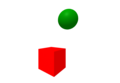
A-Frame uses the typical Cartesian coordinate system. The camera is positioned in looking in the negative direction. The sizes are all in meters, so the height of the camera is , which should be approximately at the eye level of a human. Example Program 2 shows a green sphere and a red cube positioned in and . The coordinate of the objects is equal to the height of the camera, and corresponds to distance from the camera in direction. As you can see from the code, a sphere of radius was created and for the cube the dimensions were not specified, so a cube of standard sizes was created.


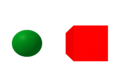
A-Frame provides a lot of the transformations such as rotation or scaling. As can be seen in Example Program 3, the sphere has been stretched in the direction by slight modification, and the cube has been rotated by about its own axis. Here it is important to note that when rotated, the own local axis through the center of the square was used and not the global coordinate system.

Example 2
[edit | edit source]
<a-scene>
  <a-box position = "1 1.6 -2"
         color="red">
  </a-box>
  <a-sphere radius="0.5"
            position="-1 1.6 -2"
            color="green">
  </a-sphere>
</a-scene>
Example 3
[edit | edit source]
<a-scene>
  <a-box position="1 1.6 -2"
         color="red"
         rotation="0 45 0">
  </a-box>
  <a-sphere radius="0.5"
            position="-1 1.6 -2"
            color="green"
            scale="1 2 1">
  </a-sphere>
</a-scene>
Das ist einer der wesentlichen Punkte in der Entwicklung mit A-Frame – man muss immer den Überblick behalten, welche Figuren bezüglich welcher Koordinatensysteme definiert sind. Um dies zu verdeutlichen, wird das Beispielprogramm 4 betrachtet. Dieses produziert beim ersten Hinschauen genau dasselbe Bild wie Beispielprogramm 2, allerdings ist hierbei die Kugel innerhalb des Würfels definiert, d. h. innerhalb des <a-box>...</a-box>-Tags. Somit ist die Kugel als Teil der Würfelgeometrie zu verstehen. Dieses Phänomen ist als Vererbung bekannt. Die Kugel vererbt unter anderem das Koordinatensystem des Würfels: Der -Punkt der Kugel ist mit dem Zentrum des Würfels bestimmt. Wie in Zeile 5 zu sehen ist, muss die Kugel um in die -Richtung verschoben werden, damit man dieselbe Geometrie bekommt, wie im Beispielprogramm 2. Die Kugel ist ein Teil der Würfelgeometrie, die Drehung des Würfels impliziert die Drehung der Kugel um die -Achse des Würfels, wie im Beispielprogramm 5 zu sehen ist.


Example 4
[edit | edit source]<a-scene>
<a-box position="1 1.6 -2"
color="red">
<a-sphere radius="0.5"
position="-2 0 0"
color="green">
</a-sphere>
</a-box>
</a-scene>
Example 5 - Rotation and Dependencies
[edit | edit source]
<a-scene>
  <a-box position="1 1.6 -2"
         color="red"
         rotation="0 -45 0">
         <a-sphere radius="0.5"
                   position="-2 0 0"
                   color="green">
         </a-sphere>
  </a-box>
</a-scene>
This definition shows how to bind an object to the axis of another object. This is especially important if you want to implement the movements of one object in relation to the other. However, it is still to be clarified how to rotate one object with respect to the axis of the other without the other rotating itself. One way to implement something like this is to use <a-entity>. The idea is to create a placeholder for an object, analogous to Example program 5 to rotate another object to rotate the placeholder. The static object is simply positioned above the placeholder. Example program 6 shows a sphere that is rotated with respect to the axis of the cube, but the cube is not.
Example 6 - Entity Concept
[edit | edit source]
<a-scene>
  <a-entity position="1 1.6 -2"
            rotation="0 -45 0">
            <a-sphere radius="0.5"
                      position="-2 0 0"
                      color="green">
            </a-sphere>
  </a-entity>
  <a-box position="1 1.6 -2"
         color="red">
  </a-box>
</a-scene>
Such a <a-entity> placeholder can also be useful when importing the 3D objects. The example 7 illustrates how to import an object in GLTF format into A-frame and position it correctly. The tree model was downloaded from Don McCurdy.
Example 7 - Import GLTF Models
[edit | edit source]
<a-scene>
  <a-entity position="0 1.6 -5"
            gltf-model="tree.gltf">
  </a-entity>
</a-scene>
The <a-entity>... </a-entity> tag is part of the so-called Entity Component System Concept (ECS). The concept is largely used for the development of computer games and carries the same philosophy as object-oriented programming: inheritance and hierarchy. It turns out that the type of structure of the code can be very helpful in many aspects. As you have already seen, one of the most important aspects is that the objects within the entity get a local coordinate system, and therefore the code is independent of the global coordinate system. When working on large projects, you don't necessarily want to declare all geometric objects in the same place with respect to the same coordinate system, but you want to divide the scene into several such entities and edit them separately.
Textures
[edit | edit source]The purpose of 3D modeling is often to visualize the realistic 3D objects. In order to make them as realistic as possible, textures are often used. A texture is an image that is projected onto the surface of each figure to reproduce physical fabric or material. Typical examples are wood, metal, rock, etc. In example 8, you can see a cube that looks like it's made of bricks. Inserting textures is done using an src option, as shown in line 5.
Example 8 - Textures
[edit | edit source]
However, as you can see in the picture above, the brick surface looks quite flat and thus artificial. To achieve the visual 3D effect, so-called "normal maps" are used. "Normal mapping" refers to the trick that modifies the reflection of the light and thus gives the surface a sublime impression. The use of normal maps is in example program 9; the application of normal maps can be accomplished with the normal-map option, see line 6.
<a-scene>
  <a-box position="0 1.6 -1.3"
         rotation="0 30 0"
         color="white"
         src="bricks.jpg">
  </a-box>
</a-scene>
You can observe that the surface looks much more realistic in the following example 9. The texture and normal map required for this was downloaded from [1].
Example 9 - Textures - normal maps
[edit | edit source]
<a-scene>
  <a-box position="0 1.6 -1.3"
         rotation="0 30 0"
         color="white"
         src="bricks.jpg"
         normal-map="bricks_nm.jpg">
  </a-box>
</a-scene>
There are many more options to enhance the visual appearance of the materials. There are good tutorials in Pasquariello, such as the documentation on the A-Frame website [2] . However, one more thing has to be noted: The texture (the image) is glued to the entire surface and thus the scaling must be adjusted separately. If the cube is large enough, the bricks also look gigantic and unrealistic. The scaling of the texture can be implemented with repeat, as in the Example program 10. Two numbers refer to the scaling into the and directions. By scaling more in one direction, the bricks can be made thicker or thinner.
In Example 10 was scaled twice in both directions. In this context it is important to adjust the corresponding normal map accordingly.
Example 10 - Textures - normal maps adjustment on scaling
[edit | edit source]
<a-scene>
  <a-box position="0 1.6 -1.3"
         rotation="0 30 0"
         color="white"
         src="bricks.jpg"
         repeat="2 2"
         normal-map="bricks_nm.jpg"
         normal-texture-repeat="2 2">
  </a-box>
</a-scene>
Example 11 - Textures - normal maps - alternative coding
[edit | edit source]<a-scene>
<a-assets>
<img id="bricks" src="bricks.jpg">
<img id="bricks_nm" src="bricks_nm.jpg">
</a-assets>
<a-box position="0 1.6 -1.3"
rotation="0 30 0"
material="color:white;
src:#bricks;
repeat:2 2;
normal-map:#bricks_nm;
normal-texture-repeat:2 2">
</a-box>
</a-scene>
Often all the material appearance options are defined in material and the images are introduced into <a-assets>, see Example program 11. The Sample program 10 and Example program 11 have exactly the same effect, but the second one emphasizes more structure, which makes the code more readable. Likewise, the second version is more canonical if you use the same textures multiple times. In particular, the pre-definition of texture images as so-called assets (files used such as images, videos, music) are advantageous for memory management.
Simple Dynamics and Animations
[edit | edit source]A-Frame is not only for the creation of static 3D objects, but also allows certain animations. The pre-programmed animations in A-Frame can be divided into two categories: motion and appearance [3]. A-Frame also allows certain interactions with the user; e.B. the mouse can serve as a trigger for one or more animations. However, this is not considered here.
The following explains the four types of animation that are most important: rotation, straight-line movement, color and shape changes. It should be noted that the notation with <a-animation> tag, as used in Pasquariello, is no longer possible from version 0.9.0.
<a-scene>
  <a-box color="red"
         position="0 0.6 -3"
         animation="property:rotation;
                    to:0 360 0;
                    easing:linear;
                    loop:true;
                    dur:5000">
  </a-box>
  <a-sphere color="green"
            radius="0.5"
            position="-1 2.6 -3"
            animation="property:position;
                       to:1 2.6 -3;
                       easing:easeInOutSine;
                       dir:alternate;
                       loop:true;
                       dur:2500">
  </a-sphere>
</a-scene>
-
 Simple animation 1
 -
 Simple animation 2


In Example Model 12 shows two animation operations: The cube rotates around its own axis and the sphere moves from left to right and back. The introduction of the animations is with the keyword
<animation> implemented, see lines 4 and 13. The type of movement is defined by <property>; the example looks at the rotation and linear movements that are marked with the keywords <rotation> and <position>.
The keyword <to> refers to the final state of the animation; for the cube, the final state would be a rotation around around the axis, and for the sphere, the coordinate of the endpoint. The keyword <dur> indicates in milliseconds how long the animation should last. In this case, it is for the cube and for the sphere.


With <loop> you can specify how often the animation should run. If you set the value to <indefinite>, the animation repeats itself infinitely many times. With <easing> you can control the speed change of the simulation, e.B. with linear the speed remains constant throughout the simulation process, and with <easeInOutSine> the speed changes sinusoidally, i.e. the speed at the beginning and at the end is slower than in the middle. The movement of the sphere is defined from left to right, i.e. after an iteration, the sphere jumps to the initial state.
So that this does not happen and the ball moves "undo" at the same speed to the initial state, the keyword <dir:alternate> can be used. Therefore, the simulation time of the sphere was set to , because it takes just as long back. In , in which the cube makes a whole revolution, the ball makes it back and forth once.
Example Model 13
[edit | edit source]<a-scene>
<a-box color="red"
position="1 1.6 -2"
animation="property:scale;
to:0.5 1 2;
easing:linear;
dir:alternate;
loop:true;
dur:5000">
</a-box>
<a-sphere color="green"
radius="0.5"
position="-1 1.6 -2"
animation="property:components.material.material.color;
type:color;
to:blue;
easing:linear;
dir:alternate;
loop:true;
dur:5000">
</a-sphere>
</a-scene>
-
 Einfache Erscheinungs- animation 1
 -
 Einfache Erscheinungs- animation 2


In Example Model 13 represents two types of appearance animations: changing the color of the sphere and changing the geometric shape of the cube. This works relatively analogously to Example Model 12. The scaling animation of the cube is activated with the keyword scale.
The final scaling of size was defined as: 0.5 1 2, which means that the cube is halved in the direction and doubled in the direction, the dimension remains unchanged. For the color change you have to set <components.material.material.color;. It is important to write <type:color; as it says in the documentation.
Modelling of Sky as Background Sphere
[edit | edit source]A-Frame makes it possible to construct very realistic 3D models. In the context of realistic VR, it is important to create the right background. The following explains the method of typically modeling the ground and sky, see Example Model 14.
The simplest way of soil representation is to use a plain. Creating the layer works with the A-frame command <a-plane>. It should be noted that the layer is usually created in - direction. Therefore, you have to rotate them, as it is done in line 9. The height and width parameters describe the size of the layer. To represent it realistically, you can put a texture with if necessary normal map on it; here the matching grass to the tree was found.
Example Model 14
[edit | edit source]<a-scene>
<a-entity position="0 3 -10"
gltf-model="tree.gltf">
</a-entity>
<a-plane src="gras.jpg"
normal-map="gras_nm.jpg"
height="100"
width="100"
rotation="-90 0 0"
repeat="100 100"
normal-textured-repeat="100 100">
</a-plane>
<a-sky src="lake.jpg"
radius="50"
position="0 0 0">
</a-sky>
</a-scene>

To represent the sky, the <a-sky> tag is usually used, see line 13. It is nothing more than a large sphere with a radius that is large enough. In this example, such a texture was used – in the form of a image (see Aframe Sky).
Augmented Reality with AR.js
[edit | edit source]It is assumed that the learner has got already the impression how A-Frame can be used as very versatile yet relatively easy to use instrument to create VR scenes for digital learning environments. Only the tip of the iceberg was considered because we touched the basic elements of modelling only. The functionality of A-Frame has more features but in terms of learning environments it is necessary to address the objective visualization first. The workload should be reduced to collaborative work and sharing through Open Educational Resources. In particular, you may want to create the AR content with minimal modifications from an existing model applying just minor modification of the given model. As already mentioned, AR is augmented reality, i.e. augmented reality with virtual components. The virtual components should be design in modular way so that they can be reused (see also FAIR principle)
One of the possibilities is to use the image of the camera as the background of the scene. However, the proposed solution is relatively complex and not easy to understand for people without good previous knowledge of web programming. Likewise, the result is quite distorted, because standard cameras produce a normal flat image that is projected onto the sphere. In Example Model 14 was a special distorted image used for exactly that reason.
A canonical approach in the A-frame community is AR.js library. This offers a simple A-frame-like interface for creating AR content and also includes marker tracking features. The markers are used to define the position and size of the VR object. The marker is detected and the position of the VR object is bound to the position of the marker; the movements and rotations of the marker are then transferred to the object. In particular, the marker is used to detect the transformation in direction - if the marker becomes smaller, the object moves further away. Markers thus serve as anchors for the object in 3D space.
Theoretically, you can reconstruct 3D information from 2D images without markers; there are enough research materials in this direction. Likewise, markerless AR has already been achieved in AR .js Jerome Etienne, but this technology is still relatively new and is not yet officially supported. The tutorials are relatively complex and incomprehensible. For these reasons, the focus is only on marker-based modeling.
Integration of AR.js in A-Frame
[edit | edit source]Using AR.js in A-Frame is relatively easy, there are several tutorials, e.B. Jerome Etienne ,Documentation. Based on Etienne, a minimal example was given in Example Model 15. The example draws a cube as soon as the "Hiro" marker is shown in the camera, see Figure Example Model 15.
It can be seen that the difference between AR ( Example Model 15) for VR ( Example Model 1)
4-line code.
First, the AR.js library is connected here on line 5, and the <embedded arjs> option on line 9. Secondly, you have to give the camera the command to look for a <"hiro"> marker; this happens in line 11. Likewise, you should place the camera in position so that it looks as if the object is above the marker as it happens in line 13. Hiro is classically used as an example, but you can make any pattern into markers. This will be explained in more detail in the next subchapter.

Example Model 15
[edit | edit source]<<!DOCTYPE html>
<html>
<head>
<script src="https://aframe.io/releases/1.1.0/aframe.min.js"></script>
<script src="https://jeromeetienne.github.io/AR.js/aframe/build/aframe-ar.js">
</script>
</head>
<body>
<a-scene embedded arjs>
<a-marker preset="hiro">
<a-box> </a-box>
</a-marker>
<a-camera position="0 0 0"> </a-camera>
</a-scene>
</body>
</html>>
-
 Verwendung von "Hiro" Markern 1
 -
 Verwendung von "Hiro" Markern 2


Generate your own Marker
[edit | edit source]The Hiro and Kanji markers are predefined and are used by the following lines to represent the 3D objects.
<a-marker preset="hiro"><a-marker preset="kanji">
However, they can be replaced by other markers, which may make it easier to see which 3D models are displayed on the respective marker.
The two supported ways to use self-created markers are:
- Patterns and
- Barcodes.
Pattern
[edit | edit source]The patterns as square image patterns should meet the following requirements:
- (Black border) Any image qualifies as a marker as long as it has a black border Etienne.
- (No symmetry regarding rotation) A marker should not have symmetry with regard to rotation by 80,180 or 360 degrees, otherwise the 3D model cannot be used on the marker pattern in be clearly displayed so that the 3D object in the camera image can be clearly represented on the marker.
- (pattern details) A 3D object should be able to be displayed at different distances on the marker in the camera image. If the detail on the marker is too fine, a webcam with the given resolution may no longer be able to resolve the marker orientation in space at a greater distance from the camera.
- (contrasts) In a camera image, different shades of gray are recognizable by illumination and incidence of light even on a white paper (e.B. shadows). If the contrasts between the colors used are large, the recognition accuracy increases. Therefore, in poor lighting conditions, the use of coarse, non-rotationally symmetrical black-and-white patterns is recommended.
Instructions for your own marker creation
[edit | edit source]The AR.js development team published Marker Generator a detailed guide to the development of the markers, which can be largely used as a guide.
Three different pattern markers were generated and tested using the marker generator Jerome Etienne. Using the generator Etienne is very simple: you upload any image and get back a *.patt and *.png file of the marker.
Recognition accuracy
[edit | edit source]Three markers have been created for this learning resource. Of these, the Irina marker completed the best: it was detected the fastest, and there were hardly any delays in movements.
However, none of the created markers performed as well as the standard Hiro and Kanji markers. The reason for different accuracy is the color contrast, which must be relatively strong and symmetry of the pattern. Lighter colors are recognized less accuracy within the camera image. Furthermore, it is essential that the marker must clearly define which side defines "FRONT", "LEFT", "RIGHT", "BACK" with respect to the symmetry of the inner marker image. The first marker in the following figures is not unambiguous in this respect.
Marker examples with different properties
[edit | edit source]-
 Eigene Pattern-Marker 1
 -
 Eigene Pattern-Marker 2
 -
 Eigene Pattern-Marker 3


Assignment of 3D models to a marker
[edit | edit source]After the marker generation, you have to tell the AR.js and A-frame that the generated pattern is a marker. This is very easy to achieve that by replacing: <a-marker preset="hiro"> in line 11 of Example Model 15 by the following line:
<a-marker type="pattern" url="marker.patt">
With <type="pattern"> you say that the marker is of the pattern type and with the <url="marker.patt"> you specify the address in which the generated *.patt file is located.
A disadvantage of patterns is that the patterns are represented by complex images. If the markers do not differ so much, it is often difficult to differentiate them from each other. In principle, an image is nothing more than a high-dimensioned matrix, the reconstruction or approximation of which is based on complicated algorithms, and is usually not even made. The distinction between images is made on the basis of certain characteristics, so that two different images with the same characteristic features cannot be distinguished at all. With a simple small-sized image (e.B. pixels), on the other hand, the pattern is much easier to recognize.

Such images, whose patterns are clearly recognizable, are called barcodes. There are different types of barcodes. Today, a distinction is made between 1D barcodes (classic barcodes that are used e.B. in shops to identify products), 2D barcodes (e.B. DataMatrix or QR), and 3D barcodes (e.B. colored 2D barcodes).
In AR.js, grid/matrix markers are supported similar to an QR code. These are even recommended in scenes with multiple markers Etienne for the reasons mentioned above. It must be noted that such patterns are classically associated with a number. For example.B. you can encode the numbers 0-63 using 3-checkerboard-like barcodes. Therefore, line 11 in the program Example Model 15 for barcodes, for example, as follows:

<a-marker type="barcode" value="5">
The line means that the camera will search for the barcode that corresponds to a <"5">.
Likewise, for barcodes, the more precise specification of the marker must be specified in line 9:
<a-scene embedded arjs="detectionMode:mono_and_matrix; matrixCodeType:3x3;">>
It also says that the marker is black and white and has a structure, i.e. a chessboard with 9 squares. The markers with the numbers 0-63 can be found in [4].
You can also use , - or patterns if you need more than 64, 8192, or 4194304 different markers. The Barcode Generator [5] generates different barcodes in different shapes. The illustrations show various barcode marker examples generated using the barcode generator.


-
 Eigene Barcode-Marker
 -

-


Example: Sun-Earth-Moon Dynamics
[edit | edit source]In this chapter, a sun-earth-moon model is considered: the earth rotates around the sun and the moon rotates around the earth. In the scientific literature, this model is known as the three-body problem. The objects also rotate around their own axis. This simulation is well suited for fourth grade elementary school students who are asked to learn the basics of planetary motion. The example can be extended to the entire solar system with little effort. Before the implementation is explained, the model under consideration is first described in more detail.
Description of the Model
[edit | edit source]
The exact dynamics of these movements depend on the geometric subject area of the Cycloids (see animation). For the sake of simplicity, the following is adopted:
- All three objects are spherical.
- The movement of all three bodies takes place in the plane.
- The orbits of the planets are circular and the speed of movement is constant.
- All rotations are parallel to the axis; i.e. the inclination of the axes is neglected.


In order to better illustrate the problem, the sketch was made.
-
 Sonne-Erde-Mond-Dynamik

The , and refer to the radii of the objects. The distances and denote the distances from the Earth to the Sun and from the Earth to the Moon. refers to the time when the Earth makes a full revolution around the Sun. refers to the time it takes to fully orbit the Moon around the Earth. The moon does not rotate around its own axis. It is known that man only gets to see one and the same side of the moon.


However, the Earth rotates around its own axis. Their rotational speed is referred to by the period time . Likewise, the dimensions are not scaled to scale to create a better illustration. The size of the Earth is negligible compared to the size of the Sun; the true-to-scale scaling would mean that the Earth and the Moon cannot be recognized. All sizes used are selected as indicated in the table.


Implementation procedure
[edit | edit source]To illustrate the problem in A-Frame, three placeholders for sun, earth and moon are needed; hereinafter referred to as Entity 1, Entity 2, and Entity 3. Entity 1 is used to describe the movement around the sun. Within Entity 1, Entity 2 is placed, moved by . Thus, Entity 2 rotates around the axis in the center of Entity 1. Within Entity 2, a rotation is also defined and Entity 3, shifted by , is placed.
This example can probably be realized without the entity concept in exactly the same way as it was in Example Model 12, however, the entities provide moving local coordinate systems, so that the objects only have to be placed correctly.
In order to better illustrate the idea, the following algorithm was produced as pseudocode.
Algorithmus 1 - Pseudocode of Sun-Earth-Moon Movements
[edit | edit source]Start Entity1
Set Position =
Rotation =
Sun
Start Entity2
Set Position =
Set Rotation =
Earth
Start Entity3
Set Position =
Moon
Ende Entity3
Ende Entity2
Ende Entity1


Likewise, the above psedocode would mean that the rotational speed of the moon around the earth would be equal to the rotational speed of the earth around its own axis. This means that the moon is only ever seen from one side of the earth. Therefore, the rotation within Entity 2 is allowed to correspond to the speed at which the moon orbits the Earth. The rotation of the earth around its own axis is adjusted accordingly with the internal additional rotation (within the sphere environment).
It should be noted that the objects also rotate by rotating the placeholders. For example, when the sun is placed within Entity 1, as shown in algorithm 1, the sun rotates with it. This can be circumvented by inserting an internal counter-rotation within the solar sphere, or by placing the sun outside Entity 1, as in Example Model 6. This technique is also used here.
The program code is available in Example Model 16.
Example Model 16
[edit | edit source]<a-scene>
<a-sphere radius="0.5"
src="sonne.jpg">
</a-sphere>
<a-entity animation="property:rotation;
to:0 360 0;
dur:100000;
loop:true;
easing:linear">
<a-entity position="1 0 0"
animation="property:rotation;
to:0 360 0;
dur:10000;
loop:true;
easing:linear">
<a-sphere radius="0.125"
src="erde.jpg"
animation="property:rotation;
to:0 360 0;
dur:1000;
loop:true;
easing:linear">
</a-sphere>
<a-entity position="0.3 0 0">
<a-sphere radius="0.0525"
src="mond.jpg">
</a-sphere>
</a-entity>
</a-entity>
</a-entity>
<a-sky radius="50"
src="sternhimmel.jpg"
repeat="20 20">
</a-sky>
</a-scene>
-
 Planetensystem 1
 -
 Planetensystem 2
 -
 Planetensystem 3


It can be noted that Entity 3 is not necessarily needed. You can also place the moon in position ). However, Entity 3 gives us a certain freedom: For example, you can use it to realize the rotation of the moon around its own axis. To make it as realistic as possible, textures for planets and a constellation for the sky were used, which can be found in Texture Universe. Here normal maps have been omitted, as the effect is hardly visible.

Marker-based realization
[edit | edit source]The model can also be transferred to markers. Example Model 17 shows how the developed sun-earth-moon model can be projected onto Hiro markers. The steps required for this are exactly as described in the chapter "Augmented Reality with AR.js", and are therefore not repeated.
Using the background is superfluous in AR, eliminating <a-sky>.
<a-scene> embedded arjs>
 <a-marker preset="hiro">
   <a-sphere radius="0.5"
             src="sonne.jpg">
   </a-sphere>
   <a-entity animation="property:rotation;
                        to:0 360 0;
                        dur:100000;
                        loop:true;
                        easing:linear">
     <a-entity position="1 0 0"
               animation="property:rotation;
                          to:0 360 0;
                          dur:10000;
                          loop:true;
                          easing:linear">
       <a-sphere radius="0.125"
                 src="erde.jpg"
                 animation="property:rotation;
                            to:0 360 0;
                            dur:1000;
                            loop:true;
                            easing:linear">
        </a-sphere>
        <a-entity position="0.3 0 0">
          <a-sphere radius="0.0525"
                    src="mond.jpg">
          </a-sphere>
        </a-entity>
      </a-entity>
    </a-entity>
  </a-marker>
  <a-camera position="0 0 0"> </a-camera>
</a-scene>
-
 Planetensystem am Hiro-Marker 1
 -
 Planetensystem am Hiro-Marker 2
 -
 Planetensystem am Hiro-Marker 3


Acknowledgement
[edit | edit source]This is a translation of the work[2] of Irina Shashkova in the german Wikiversity.
See also
[edit | edit source]- 3D Modelling
- Examples of 3D Modelling
- FAIR principle - Findable Accessible Interoperable Reusable
- Augmented Reality on Markers
- Real World Lab
- Cycloid
- Digital Learning Environment
References
[edit | edit source]- ↑ Chen, P., Liu, X., Cheng, W., & Huang, R. (2017). A review of using Augmented Reality in Education from 2011 to 2016. Innovations in smart learning, 13-18.
- ↑ AR VR in der Grundschule. (5. Dezember 2022). Wikiversity, . Abgerufen am 10. Januar 2023, 18:10 von https://de.wikiversity.org/w/index.php?title=AR_VR_in_der_Grundschule&oldid=873622.