
Engineering Projects/Power projects/Howard Community College/Spring2012/p1550KMN
Problem Statement
[edit | edit source]Developing power supply apparatus solutions for other projects.
Converting a computer power supply to a lab power supply.
Team Members
[edit | edit source]Summary
[edit | edit source]Computer power supplies cost around US$30, but lab power supplies can run you $100 or more! By converting the cheap (free) ATX power supplies that can be found in any discarded computer, you can get a phenomenal lab power supply with huge current outputs, short circuit protection, and reasonably tight voltage regulation on the 5V line.
Poster
[edit | edit source]
Story
[edit | edit source]We converted three ATX power supplies to LAB ones, and fortunately all of them work perfectly. Here is the detailed process:
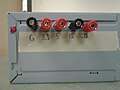
First, the power supply should be opened. then, all wires were made shorter. Next, a 20 ohm power resistor was connected to a red and black wire. The power resistor helps to discharge capacitors, so the possibility of getting electrical shock decreases. After that, the green wire was shorted to a black wire to turn on the power supply. If you got a switch, it would be better to connect them to the switch. Next, the gray wire was connected to the Cathode of a LED, and a 360 ohm resistor was connected to the Anode of the LED while the resistor was connected to a black wire. For determining Cathode and Anode of a LED, we used the "diode" feature of a multimeter. If a multimeter is connected correctly to a LED, the LED turn on, so you can realize which leg is Cathode, or positive, and the other leg is Anode, or negative. Then, all remaining same-color wires were gathered and connected to each other; blacks, reds, oranges, yellows, and blue go with each other. The most challenging part of the project was drilling holes on the case of the power supply. It was a little difficult because we wanted to drill holes on metal. We used 2-3 different size of drills from thin to thick and used water for cooling down the drills. After drilling 6 holes, 5 for binding posts and 1 for LED, we attached binding posts to them and connected each wire to each binding post. We soldered all connections. We placed the LED to its hole and closed the power supply. Then, we labeled binding posts. Finally, we plugged it in and checked the output voltage of each binding posts by a multimeter. Black is ground; orange is 3.3 volt; red is 5 volt; yellow is 12 volt; and blue is -12 volt. We did same process for the 2 other power supplies.
We confronted several obstacles during this projected. First, we started working on one power supply, so one of us was able to take it home and work on it, and the other one had to do research about it. Therefore, from the 2nd week we decided to work on two power supplies, so both of us were able to take a power supply home over weekends. The 2nd obstacle was that we only found one 20 ohm power resistor and used it in the first power supply, so we've got to parallel two 20 ohm resistors in order to get the same resistance in the circuit for the 2nd and 3rd power supplies. The third problem was about the power supply itself. Two of our power supplies were DELL, and they had a big transformer which was attached to the top of their cases, so we got less room for our work. The 4th problem was that the LED hole of the first power supply was in the way of putting the ATX power supply together. So we had to shift the hole to another location.
When each power supply finished, we tested the output voltage of their binding posts by a multimeter. Black is ground; orange is 3.3 volt; red is 5 volt; yellow is 12 volt; and blue is -12 volt. Also, other combinations of two binding post give different voltage. For instance, 5 volt with 12 volt give 7 volt; 12 volt with -12 volt give 24 volt and so on. In addition, their LED's work properly. Two power supplies' LED turn on steady and one of them blinks.
Decision List
[edit | edit source]List all formal decisions made with links to their documentation such as a decision tree or decision matrix.
1. For the first weekend, we decided that one of us take the power supply home and work on it, and the other one do some research about power supplies's safety:
2. The 2nd week we decided to start converting another power supply while we were still working on the first one.
Start working on the 2nd power supply
-
 Still working on the first one

3. The 3rd week, after finishing the 2nd power, we decided that one of us shift to the 3rd power supply and the other wrap up the first one.
-
 the 2nd power supply
 -
 the 3rd power supply
 -
 wrap up the firs one


Material List
[edit | edit source]An ATX power supply of any rating above 150 Watt (can be found from an obsolete computer, online, or at your local computer store)
Wire cutters
Needle nose pliers
Drill
Reamer
Soldering Iron & Solder
Electrical Tape
Heat Shrink Tubing & Heat Gun (optional but would recommend)
Binding posts
LED (optional)
Current limiting resistor for the LED (330 ohms)(optional, only need if adding a LED)
Power resistor to load the power supply
Low Wattage Switch (optional, but helps to turn on and off the output of the power supply.)
Computer Power Cable
Software List
[edit | edit source]No Actual software was used besides web references.
Time
[edit | edit source]30 hours
Tutorials
[edit | edit source]Here is a good tutorial web page for converting a ATX power supply to a LAB power supply
ATX Power Supply to a Lab Power Supply Video on how to convert an ATX power supply to a Lab power supply
Next Steps
[edit | edit source]I would definitely recommend others who take this project to:
1. Solder all connections carefully. w/o soldering, wires will be easily disconnected, so the power supply will not work.
2. Use 2-3 different size of drills from thin to thick. First, make holes with the thin one and then make them bigger by the thicker one. Also, each 2 or 3 seconds, cool down the drill by oil or water. If you do not cool them down, the drills get too hot and start melting, so they lose their sharpness.
3. Use heating gun and shrink tube for covering all stripped wires and connections.
4. Be careful not to touch Capacitors or other interior parts of the power supply's board.
Edit by Kris: Be a Ninja