
Autonomous Power Wheel
Problem
[edit | edit source]Motor vehicle accidents are the leading cause of death for young adults in the United States. Google has developed full-sized self-driving vehicles that are street-legal in Nevada. Stanford's autonomous vehicle won the DARPA Grand Challenge in 2005.
Project Goal: Design and implement the electro-mechanical systems and software required to control a Power Wheel. The autonomous vehicle should be able to travel outdoor on specified paths while avoiding obstacles.
-
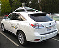 Google's Lexus RX 450h Self-Driving Car

Conceive
[edit | edit source]The Power Wheel (electric ride-on toy) must be able to autonomously drive around the campus of Howard Community College in Columbia, MD. Initially, the car will be confined to a flat open space (e.g. parking lot). The final design should be able to navigate to specified waypoints while avoiding obstacles.

Design Requirements for each Component or Subsystem
|
|---|
|
The goal of the project is to materials, designs, and data gathered by past groups to create a design for steering controls, pedal controls, and to have them controlled and powered by an Arduino and a Monster Motor Sheild.
Steering:
Pedal:
|
Design
[edit | edit source]The design phase involves designing subsystems in order to make the power wheel autonomous. It is obvious that these subsystems have to be able to work together with ease. In doing so, we anticipate that at some stage, the vehicle will be able to drive autonomously without any operator instructions. However, as it stands now, several subsystems must first be designed in order to replace the interactions a human driver would have. These subsystems must be both simple to build, simple to repair and improve upon.
Design Concepts for Subsystems
[edit | edit source]Steering actuation concepts
|
|---|
|
There were four initial designs for the steering mechanism: linear actuator pulling and pushing a chain, linear actuator attached to steering wheel, lever with the linear actuator, and direct rotary actuation from a high-torque motor. Steering Concept #1 This concept would use a track built around the perimeter of the Power Wheel's steering wheel. Inside the track will be a bicycle chain that was attached at one end to the steering wheel and to the other end the linear actuator. As the linear actuator would extend the chain would move forward in the track and push on the steering wheel and cause the steering wheel to turn. As the actuator retracts it would pull on the chain and that would turn the steering wheel in the opposite direction. This concept would provide the greatest movement of the steering wheel and have the tightest turning radius. The design would also be compact and not add much bulk to the overall design. The fault with the design was the complexity of the construction, the complexity of installation and removal, and overall cost. To make a track and use the chain, there needs to be metal work done, which the engineering workshop is not equipped. The design would be hard to install and remove, and one of the criteria be it could easily be removed from the Power Wheel. Since the workshop is not equipped with the equipment or materials for a prototype to be built, the cost was more than what our budget allowed.
Steering Concept #4 The fourth design turns the steering wheel using a direct attachment to a high-torque. The power window motor from a standard automobile is one option for the actuating motor.  |


Gas Pedal actuation concepts
|
|---|
|
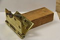
There was the original design of the pedal pusher, form past groups, utilizing a pedal pusher with side brackets attached. An alternative design was made using a rectangular pedal piston and a square bracket. Pedal Concept #1 The original design was a pedal pusher with side brackets built on to the pusher. The brackets were on either side of the pedal pusher and was made to go on each side of the pedal. The pedal pusher will have hollow center to allow the screw from the motor to fit inside the pusher. There will also be a cut out on the side to allow access for a nut that will attach to the screw mechanism of the motor. As the motor turns the screw, the nut will extend and move the pedal pusher. The brackets were used as a way to stop the pedal pusher from spinning. The Concept with the use of a pusher and the screw motor worked properly, but the brackets caused the design to fail. Parts of the concept was used to build the second design, the pedal piston and bracket. Pedal Concept #2 The new design was a pedal piston. It was shaped as a rectangular cube and was hollow to allow the screw mechanism form the motor to be inserted into the piston. There was also a cut out on the side, similar to the cutout from the original design, that allowed access for the nut to be attached to the screw mechanism. To resolve the issues the last design had with the built on brackets, the new design uses a separate square mounting bracket. The bracket will have the piston inserted and will prevent the piston from spinning and not extending, secure the bracket to the mounting platform, and guide the piston to the pedal. |


Ultrasonic Sensor Mounting
| ||||||||||||||||||||||||||||||||||||||||
|---|---|---|---|---|---|---|---|---|---|---|---|---|---|---|---|---|---|---|---|---|---|---|---|---|---|---|---|---|---|---|---|---|---|---|---|---|---|---|---|---|
|
There were three choices for the mounting platform: 1) wooden mount, 2) rotating mounting bracket, and 3) the mounting plate.
The wooden mount design will be a wooden stand that would attach to the floor of the lower platform in the Power Wheel. It will extend over the front of the Power Wheel to allow the Ultrasonic Sensor HC-SR04 Distance Measuring Module to have an unobstructed view of what is in front of the Power Wheel. At the top of the wooden mount the Ultrasonic Sensor HC-SR04 Distance Measuring Module will be attached with small wood screws to secure it and prevent it from moving while the Power Wheel is driving.
This concept uses a rotating mounting bracket for the Ultrasonic Sensor HC-SR04 Distance Measuring Module. The sensor will be forward facing while the Power Wheel is driving. When the sensor encounters an obstacle it will stop the Power Wheel and put it in reverse, as the Power Wheel reverses the sensor will sweep back and forth 180° and determine which direction the Power Wheel will need to go to navigate around the obstacle. The whole setup, with the rotating mounting bracket and the Ultrasonic Sensor HC-SR04 Distance Measuring Module, will be mounted on a wooden stand on the lower platform of the Power Wheel.
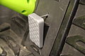
The mounting plate will extend down under the Power Wheel and allow room to attach the ultrasonic sensor. The mounting plate will be mounted using the bolt pattern of front bumper on the Power Wheel. The front bumper will be removed and a piece of plywood will be attached, as a mounting plate, using the same bolt pattern as the bumper. The bumper will be reattached on top of the mounting plate with the longer bolts.At this mounting position it will be able to sense curbs and other low lying obstacles. The mounting plate will also need to protect the ultrasonic sensor from collisions. The mounting plate will have brackets on either side of the ultrasonic sensor, that will extend further than the sensor. Decision Matrix
For the final choice for the design concept was the Wooden Plate, it had the best range of sensor and function and be able to have future groups to add more capabilities of the rotating mounting bracket to platform. |
Experimental prototypes and testing
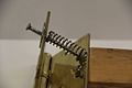
[edit | edit source]- Video of power window motor turning steering wheel. Testing was successful, but the power window motor was inadvertently damaged and this concept was abandoned.
- Steering Wheel Mock-up for Testing


- Gas Pedal Prototype
-

-
-
-

-

-
 Compressed Pedal
 -
 Compressed
 -
 before on actual pedal
 -
 after on actual pedal


Gas Pedal Presser Test Video http://youtu.be/gIV6zhy3gRI
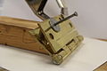
- Base Prototype


The final design
[edit | edit source]Steering actuation
|
|---|
|
The finalized design will be used for the steering will be Steering Concept #3. It will use only three parts: the lever, mounting brackets, and the linear actuator. The use of the lever will allow for adequate torque as the angle changes between the lever and the linear actuator. |

Pedal actuation
|
|---|
|
The finalized design will be used for the project will be Pedal Concept #2. This will use the pedal piston and the square mounting bracket. This will allow for piston to move back and forth by the turning of the screw and nut, and with the use of the square bracket it will be secured, guided to the pedal, and prevented from spinning. The initial design for the bracket was modified to include extensions of the bracket that will be drilled and screwed in. These extensions allow for the easy removal of the bracket on the platform.
|


Support structure
|
|---|
|


Utilization of Knowledge in Design
[edit | edit source]Technical details and scientific principles
[edit | edit source]Torque/Force Calculation for Steering Actuation
|
|---|
|
The steering controls will need to use the Firgelli Miniature Linear Actuator and must fall within the constraints of the linear actuator. The stroke length of the actuator is 140 mm and to steer in both directions with restricting the actuator to using half the stroke length in each direction, 70 mm. The steering wheel itself in the power wheel, measured by the past groups, is 86.6 N at 8.3 cm to turn the steering wheel. Using the equation   The amount of torque can be calculated to find the actuator was capable of pulling back the steering wheel at that length. But further research into the design and the options how to mount the actuator on the steering wheel we need to have two pivot points, one at the base of the actuator and one at the point where the actuator and the lever connect. With that, the actuator will not be always perpendicular with the lever to apply the force. We need to account for the loss of torque at different angles as the steering wheel is turned by the actuator. To find the correct length of the lever and the angles that the lever will be with the actuator I will use the equation: |
Ultrasonic Distance Sensing
|
|---|
|
The Ultrasonic Sensor HC-SR04 Distance Measuring Module is an ultrasonic range sensor for an arduiono. It detects the distance of the closest object in front of the sensor, from 2 centimeters up to 3 meters. It works by sending out a burst of ultrasound, from one "ear", and listening for the echo when it bounces off of an object, with the other "ear". The Arduino board sends a short pulse to trigger the detection, then listens for a pulse on the same pin using the "pulseIn()" function. The duration of this second pulse is equal to the time taken by the ultrasound to travel to the object and back to the sensor. Using the speed of sound, this time can be converted to the distance that can be used to stop the Autonomous Power Wheel when approaching an obstacle. |
Prior work in the field, reverse engineering and redesign
[edit | edit source]Sparkfun Electronics provides an example Arduino code for controlling two motors simultaneously using the Monster Moto Shield. This sketch was the basis for the vehicle control code:
MonsterMoto Shield Example Arduino Sketch
|
|---|
/*  MonsterMoto Shield Example Sketch
  date: 5/24/11
  code by: Jim Lindblom
  hardware by: Nate Bernstein
  SparkFun Electronics

 License: CC-SA 3.0, feel free to use this code however you'd like.
 Please improve upon it! Let me know how you've made it better.

 This is really simple example code to get you some basic
 functionality with the MonsterMoto Shield. The MonsterMote uses
 two VNH2SP30 high-current full-bridge motor drivers.

 Use the motorGo(uint8_t motor, uint8_t direct, uint8_t pwm)
 function to get motors going in either CW, CCW, BRAKEVCC, or
 BRAKEGND. Use motorOff(int motor) to turn a specific motor off.

 The motor variable in each function should be either a 0 or a 1.
 pwm in the motorGo function should be a value between 0 and 255.
 */
#define BRAKEVCC 0
#define CW   1
#define CCW  2
#define BRAKEGND 3
#define CS_THRESHOLD 100

/*  VNH2SP30 pin definitions
 xxx[0] controls '1' outputs
 xxx[1] controls '2' outputs */
int inApin[2] = {7, 4};  // INA: Clockwise input
int inBpin[2] = {8, 9}; // INB: Counter-clockwise input
int pwmpin[2] = {5, 6}; // PWM input
int cspin[2] = {2, 3}; // CS: Current sense ANALOG input
int enpin[2] = {0, 1}; // EN: Status of switches output (Analog pin)

int statpin = 13;

void setup()
{
  Serial.begin(9600);

  pinMode(statpin, OUTPUT);

  // Initialize digital pins as outputs
  for (int i=0; i<2; i++)
  {
    pinMode(inApin[i], OUTPUT);
    pinMode(inBpin[i], OUTPUT);
    pinMode(pwmpin[i], OUTPUT);
  }
  // Initialize braked
  for (int i=0; i<2; i++)
  {
    digitalWrite(inApin[i], LOW);
    digitalWrite(inBpin[i], LOW);
  }
  // motorGo(0, CW, 1023);
  // motorGo(1, CCW, 1023);
}

void loop()
{

 // Push the gas pedal for 6 seconds
  motorGo(1, CW, 1023);
  delay(6000);//time required to push the pedal

// Stop motor to leave the pushed pedal
  motorGo(1, CW, 0);
  delay(5000);//time required for the drive

////turn all the way left
//  motorGo(1, CW, 1023);
//  delay(500); //time required for half stroke length
//
////keep turning for 20 seconds
//  motorGo(1, CW, 0);
//  delay(20000);//time required for the turn
//
////turn all the way right
//  motorGo(1, CCW, 1023);
//  delay(500); //time required for half stroke length
//
////keep turning for 20 seconds
//  motorGo(1, CCW, 0);
//  delay(20000);//time required for the turn

 // Receed from the gas pedal for 6 seconds
  motorGo(1, CCW, 1023);
  delay(5500);//time required to stop the actuator from pushing

  if ((analogRead(cspin[0]) < CS_THRESHOLD) && (analogRead(cspin[1]) < CS_THRESHOLD))
    digitalWrite(statpin, HIGH);
}

void motorOff(int motor)
{
  // Initialize braked
  for (int i=0; i<2; i++)
  {
    digitalWrite(inApin[i], LOW);
    digitalWrite(inBpin[i], LOW);
  }
  analogWrite(pwmpin[motor], 0);
}

/* motorGo() will set a motor going in a specific direction
 the motor will continue going in that direction, at that speed
 until told to do otherwise.

 motor: this should be either 0 or 1, will selet which of the two
 motors to be controlled

 direct: Should be between 0 and 3, with the following result
 0: Brake to VCC
 1: Clockwise
 2: CounterClockwise
 3: Brake to GND

 pwm: should be a value between ? and 1023, higher the number, the faster
 it'll go
 */
void motorGo(uint8_t motor, uint8_t direct, uint8_t pwm)
{
  if (motor <= 1)
  {
    if (direct <=4)
    {
      // Set inA[motor]
      if (direct <=1)
        digitalWrite(inApin[motor], HIGH);
      else
        digitalWrite(inApin[motor], LOW);

      // Set inB[motor]
      if ((direct==0)||(direct==2))
        digitalWrite(inBpin[motor], HIGH);
      else
        digitalWrite(inBpin[motor], LOW);

      analogWrite(pwmpin[motor], pwm);
    }
  }
}
|
Implement
[edit | edit source]Implementation Goals
|
|---|
|
1. Finish design and building the table top platform.
|
Overview of Implementation Steps
[edit | edit source]Acquire and test linear actuator for steering
|
|---|
|
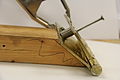
The first task was to acquire a small linear actuator. The linear actuator needed to be strong enough so that it is capable of turning right and left when it retracts and extends, respectively. It takes 86.6 newtons at 8.3 centimeters, 721.27 newtons per centimeter, to turn the power wheel both ways, which means that we needed a linear actuator that can retract and extend with the same or more amount of force. As the steering wheel turns the amount of force that was applied by the miniature linear steering wheel would change, further away from 90°, the less force was being transferred to the steering lever. The linear actuator that was purchased for this project can hold up to 200 newtons, which completes the requirement for the linear actuator. |
Finalize platform design
|
|---|
|
The next step was to finish designing the platform in the Power Wheel. Measurements were taken from the Power Wheel and used to design the platform in the Power Wheel. When the design was finalized, the platform was constructed and installed on the Power Wheel.
|


Mechanical assembly of driving system
|
|---|
|
The next step was to install all the components on the Power Wheel. After the steering and the pedal components were installed on the Power Wheel platform, the battery and the Arduino were installed. The pedal pusher assembly need to be adjusted to accommodate the wooden block that attached the lower platform to the upper platform.
|


Programming for navigating predefined path
|
|---|
|
The Arduino code was adjusted to make the Power Wheel drive in a predetermined pattern. The Power Wheel was taken outside and timed on how long it took to make turns and the speed driving in a straight line. The code was changed to make the Power Wheel to drive straight, make a right turn, drive straight again, make another right turn, and finally come to a stop with minimal interaction by the operator. The path the Power Wheel was to drive was decided to be make a right turn from side entrance of the Nursing Building and drive straight till it reached the Science and Technology Building, then make a left, and then come to a stop in front of the James Clark Jr. Library Building. |
Mounting Ultrasonic Sensor
|
|---|
|
The goal was to build the mounting plate for the Ultrasonic Sensor, attach the sensor the mounting plate, and to attach the sensor to the Arduino.
The designs for the wooden plate were made for the Power Wheel to allow for 4.5 inch of clearance under the wooden plate. This was changed and the wooden plate was raised 1 inch to allow for maximum clearance under the wooden plate, the same clearance as the axles of the Power Wheel. This is done to allow the most clearance possible, and to avoid taller objects, like grass, that could have possible obstruct the sensor and are not obstacles that would be required to avoid. This will prevent unnecessary damage to the sensor and unnecessary stops for the Power Wheel.
The ultrasonic sensor needs to be attached to the Arduino to work. To attach the ultrasonic sensor, a 4-pin plug is used. The wires for the plug were not long enough to attach to the Arduino from the mounting point of the ultrasonic sensor on the wooden plate. To solve the problem longer wires were soldered on to reach the Arduino. After the wires were attached , heat shrink was used to protect the soldering. The extension wires that were used were all the same color, so the wires needed to be labeled to denote which wire was which. |


Modify Code to Incorporate Single Fixed Distance Sensor
|
|---|
|
The code needed to be changed to allow for the use of the ultrasonic sensor. The Arduino needs to be able to run both the original code to drive and the code for the sensor at the same time. The code for the sensor should be constantly checking if there is any obstacles in the path of the Power Wheel. When an obstacle is detected it needs to pause the driving code at the point it detects the obstacle and be able to restart the code from the same point when the obstacle has been cleared. |
Hardware Manufacturing
[edit | edit source]Parts List
[edit | edit source]- Power Wheel, Fisher-Price Power Wheels Dune Racer 12-Volt Battery-Powered Ride-on, Green, $229.00 from walmart.com
- Miniature linear actuator, a Firgelli Miniature Linear Actuator L16 purchased for $70.00 from firgilli.com
- Screw motor, 12VDC, 78RPM Motor with Right Angle Leadscrew, purchased for $14.95 from mpja.com
- Ultrasonic Sensor, Ultrasonic Sensor HC-SR04 Distance Measuring Module, purchased from miniinthebox.com, for $1.98
- Arduino UNO
- Monster MotoShield, Sparkfun Electronics
- Plywood, batteries, and hardware for assembly acquired from the engineering workshop
Hardware Assembly Details
[edit | edit source]The plywood was cut to make the platform that would sit in the power wheel. The plywood is built to place the other functioning parts, such as the linear actuator, the battery, the Arduino, the wires, and the gas pedal piston. The platform, as well as the other parts, was engineered to ensure that it was easy to remove and re-install if needed. The Power Wheel platform was constructed in two parts, the upper platform to attach to the mounting plate, and a lower platform for the pedal pusher assembly. The two parts were cut from ½” plywood and attached with a section of 2x4 wood stud and attached with 1 ¼” wood screws.
After the platform was built, the steering assembly needed to be constructed. It consisted of three parts: the miniature linear actuator, the steering lever, and the wooden wedge. The steering lever was made from the same material as the platform, ½” plywood, it was attached on either side of the steering will with U-brackets, 3” bolts, and nuts. The height of the wooden wedge was calculated using measurements taken with the aid of the miniature linear actuator. The actuator was extended for seven seconds, half the stroke length, and then attached to the steering wheel lever. The distance was measured from the bottom of the miniature linear actuator to the floor of the mounting platform was measured, that distance was used to measure and construct the wooden wedge. The wooden wedge was constructed from a 2x4 wood stud, and was cut at 50° to match the angle of the steering wheel.
Finally, the last part that needed to be attached was the bracket and the pedal piston to the platform. The pedal pusher assembly was constructed from three parts: the pedal piston, the screw motor, and the mounting bracket. Both the pedal piston and the mounting bracket was constructed from PLA and printed using the MakerBot.
The mount for the Ultrasonic Sensor was added to the front of the Power Wheel. It was attached using the same bolt pattern as the front bumper, with the front bumper reattached back on top. This was done to help protect the Power Wheel and the components from collisions. The mounting plate extended under the front bumper of the Power Wheel and had wooden bumpers attached. The wooden bumpers were added to prevent damage to the Ultrasonic Sensor in case of a collision if the sensor based avoidance system failed.
The last thing that needed to go in the power wheel is the Arduino, battery, and the wires, that can make the power wheel to function as a whole.
Software Implementation
[edit | edit source]An Arduino Duemilanove and Monster MotoShield were used to control the actuators. Starting with example code (see above) for the motor shield, modifications were made to control vehicle steering and forward motion. In order to drive along a predetermined path along a sidewalk on the campus of Howard Community College, the following code was developed.
Arduino code for Quad Sidewalk Driving Demo
|
|---|
/*
//*  MonsterMoto Shield Example Sketch
//  date: 5/24/11
//  code by: Jim Lindblom
//  hardware by: Nate Bernstein
//  SparkFun Electronics
//
// License: CC-SA 3.0, feel free to use this code however you'd like.
// Please improve upon it! Let me know how you've made it better.
//
// This is really simple example code to get you some basic
// functionality with the MonsterMoto Shield. The MonsterMote uses
// two VNH2SP30 high-current full-bridge motor drivers.
//
// Use the motorGo(uint8_t motor, uint8_t direct, uint8_t pwm)
// function to get motors going in either CW, CCW, BRAKEVCC, or
// BRAKEGND. Use motorOff(int motor) to turn a specific motor off.
//
// The motor variable in each function should be either a 0 or a 1.
// pwm in the motorGo function should be a value between 0 and 255.
// */
#define BRAKEVCC 0
#define CW   1
#define CCW  2
#define BRAKEGND 3
#define CS_THRESHOLD 100
//
/*  VNH2SP30 pin definitions
 xxx[0] controls '1' outputs
 xxx[1] controls '2' outputs */
int inApin[2] = {7, 4};  // INA: Clockwise input
int inBpin[2] = {8, 9}; // INB: Counter-clockwise input
int pwmpin[2] = {5, 6}; // PWM input
int cspin[2] = {2, 3}; // CS: Current sense ANALOG input
int enpin[2] = {0, 1}; // EN: Status of switches output (Analog pin)

int statpin = 13;

void setup()
{
  Serial.begin(9600);

  pinMode(statpin, OUTPUT);

  // Initialize digital pins as outputs
  for (int i=0; i<2; i++)
  {
    pinMode(inApin[i], OUTPUT);
    pinMode(inBpin[i], OUTPUT);
    pinMode(pwmpin[i], OUTPUT);
  }
  // Initialize braked
  for (int i=0; i<2; i++)
  {
    digitalWrite(inApin[i], LOW);
    digitalWrite(inBpin[i], LOW);
  }
  // motorGo(0, CW, 1023);
  // motorGo(1, CCW, 1023);
}

void loop()
{
 //1=piston
 //0=pedal
 //CW press
 //actuator is in the middle/halfway

//turn all the way left
motorGo(0, CCW, 1023);
delay(7000); //time required for half stroke length
//// Stop motor to leave the pushed pedal
motorGo(0, CCW, 0);
delay(100);//time required for the drive
//Push the gas pedal for 1.35 seconds

motorGo(1, CW, 1023);
delay(1350);//time required to push the pedal
//// Stop motor to leave the pushed pedal
motorGo(1, CCW, 0);
delay(5000);//time required for the drive
//DEPRESS
motorGo(1, CCW, 1023);
delay(1350);//time required to push the pedal
//// Stop motor to leave the pushed pedal
motorGo(1, CCW, 0);
delay(100);//time required for the drive
//DEPRESS

//turn to neutral position
motorGo(0, CW, 1023);
delay(7000); //time required for half stroke length

//// Stop motor to leave the pushed pedal
motorGo(0, CCW, 0);
delay(100);//time required for the drive
//Push the gas pedal for 1.35 seconds

//// Stop motor to leave the pushed pedal
motorGo(1, CW, 0);
delay(40000);//stop


  if ((analogRead(cspin[0]) < CS_THRESHOLD) && (analogRead(cspin[1]) < CS_THRESHOLD))
    digitalWrite(statpin, HIGH);
}

void motorOff(int motor)
{
  // Initialize braked
  for (int i=0; i<2; i++)
  {
    digitalWrite(inApin[i], LOW);
    digitalWrite(inBpin[i], LOW);
  }
  analogWrite(pwmpin[motor], 0);
}

/* motorGo() will set a motor going in a specific direction
 the motor will continue going in that direction, at that speed
 until told to do otherwise.

 motor: this should be either 0 or 1, will selet which of the two
 motors to be controlled

 direct: Should be between 0 and 3, with the following result
 0: Brake to VCC
 1: Clockwise
 2: CounterClockwise
 3: Brake to GND

 pwm: should be a value between ? and 1023, higher the number, the faster
 it'll go
 */
void motorGo(uint8_t motor, uint8_t direct, uint8_t pwm)
{
  if (motor <= 1)
  {
    if (direct <=4)
    {
      // Set inA[motor]
      if (direct <=1)
        digitalWrite(inApin[motor], HIGH);
      else
        digitalWrite(inApin[motor], LOW);

      // Set inB[motor]
      if ((direct==0)||(direct==2))
        digitalWrite(inBpin[motor], HIGH);
      else
        digitalWrite(inBpin[motor], LOW);

      analogWrite(pwmpin[motor], pwm);
    }
  }
}
|
The second phase of software development was the incorporation of sensor data for simple obstacle avoidance. The following tutorial (https://www.youtube.com/watch?v=PG2VhpkPqoA) shows code to work the ultrasonic sensor, resulting in the serial monitor displaying numbers after the code was uploaded.
-
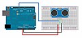 Arduino circuit with ultrasonic sensor
 -
 The serial monitor results for new code


The following algorithm was implemented to pause normal program execution when an obstacles exists in front of the vehicle.
Flowchart of algorithm for sensor-based pause of Arduino code

The algorithm shown above was then implemented in a simple Arduino program, separate from the vehicle control program.
Arduino Code to Test Sensor-Based Pausing of Program Execution
|
|---|
#define trigPin 12
#define echoPin 11
   int duration, distance;
   int led = 13;
   int starttime, elapsedtime, pausestart, pauseend, pauseduration;
void setup(){
  Serial.begin (9600);
  pinMode(led, OUTPUT);
  pinMode (trigPin, OUTPUT);
  pinMode (echoPin, INPUT);
}
void loop(){
  elapsedtime=0;
  pauseduration=0;
  digitalWrite(led, LOW);//led off
  Serial.println("Start of main loop");//debugging
  starttime=millis();// starts counting
    while (elapsedtime<7000){//while time is under 5 sec (i.etime required foro drive)
      digitalWrite(led, LOW);//led off
      digitalWrite(trigPin, HIGH);//sensor
      delayMicroseconds(1000); //sensor
      digitalWrite(trigPin, LOW);//sensor
      duration = pulseIn(echoPin, HIGH); //sensor
      distance = (duration/2) / 29.1;//sensor output
      delay(50);
       if (distance<10){//if distance is below 100 cm
           digitalWrite(led, HIGH);//turn led on
           pausestart=millis();//starts obstruction timing
         //  Serial.print(pausestart);//debugging
          // Serial.println(" pause start");//debugging
           while (distance<100){
              delay (100);//do nothing
              digitalWrite(trigPin, HIGH);//sensor
              delayMicroseconds(1000);//sensor
              digitalWrite(trigPin, LOW);//sensor
              duration = pulseIn(echoPin, HIGH);//sensor
              distance = (duration/2) / 29.1;//sensor output
              Serial.print(distance);//debugging
              Serial.println(" cm from while loop");//debugging
           }
           pauseend=millis();// ends obstruction timing
           pauseduration=pauseend-pausestart;//total wait time for obstruction
         //  Serial.print(pauseend);//debugging
         //  Serial.println(" pause end");//debugging

       }
   Serial.print(pauseduration);
   Serial.println(" wait time");//debugging
   elapsedtime=(millis()-starttime)-pauseduration; //subtract wait time from time before osbtruction
   Serial.print(elapsedtime);//debugging
   Serial.println(" elapsed");//debugging

  }
}
|
After troubleshooting, the above code was incorporated with the vehicle control code. The power wheel simply drives straight and stops before hitting an obstacle.
Arduino Code for Sensor-Based Stopping Test
|
|---|
/*
//*  MonsterMoto Shield Example Sketch
//  date: 5/24/11
//  code by: Jim Lindblom
//  hardware by: Nate Bernstein
//  SparkFun Electronics
//
// License: CC-SA 3.0, feel free to use this code however you'd like.
// Please improve upon it! Let me know how you've made it better.
//
// This is really simple example code to get you some basic
// functionality with the MonsterMoto Shield. The MonsterMote uses
// two VNH2SP30 high-current full-bridge motor drivers.
//
// Use the motorGo(uint8_t motor, uint8_t direct, uint8_t pwm)
// function to get motors going in either CW, CCW, BRAKEVCC, or
// BRAKEGND. Use motorOff(int motor) to turn a specific motor off.
//
// The motor variable in each function should be either a 0 or a 1.
// pwm in the motorGo function should be a value between 0 and 255.
// */
#define BRAKEVCC 0
#define CW   1
#define CCW  2
#define BRAKEGND 3
#define CS_THRESHOLD 100
#define trigPin 12
#define echoPin 11
//
/*  VNH2SP30 pin definitions
 xxx[0] controls '1' outputs
 xxx[1] controls '2' outputs */
int inApin[2] = {7, 4};  // INA: Clockwise input
int inBpin[2] = {8, 9}; // INB: Counter-clockwise input
int pwmpin[2] = {5, 6}; // PWM input
int cspin[2] = {2, 3}; // CS: Current sense ANALOG input
int enpin[2] = {0, 1}; // EN: Status of switches output (Analog pin)
int statpin = 4;
int duration, distance;
int led = 13;//
int starttime, elapsedtime, pausestart, pauseend, pauseduration;//

void setup()
{
  Serial.begin(9600);
  pinMode(statpin, OUTPUT);
  pinMode (led, OUTPUT); //
  pinMode (trigPin, OUTPUT);//
  pinMode (echoPin, INPUT);//
  // Initialize digital pins as outputs
  for (int i=0; i<2; i++)
  {
    pinMode(inApin[i], OUTPUT);
    pinMode(inBpin[i], OUTPUT);
    pinMode(pwmpin[i], OUTPUT);
  }
  // Initialize braked
  for (int i=0; i<2; i++)
  {
    digitalWrite(inApin[i], LOW);
    digitalWrite(inBpin[i], LOW);
  }
  // motorGo(0, CW, 1023);
  // motorGo(1, CCW, 1023);
}

void loop()
{
 //1=piston
 //0=pedal
 //CW press
 //actuator is in the middle/halfway
 //straight drive while checking for obstacle
// right drive turn
// press
motorGo(1, CW, 1023);//added
delay(1350);//time required to push the pedal 1.35 secs
motorGo(1, CCW, 0);//stop

   elapsedtime=0;
  pauseduration=0;
  digitalWrite(led, LOW);//led off
  Serial.println("Start of main loop");//debugging
  starttime=millis();// starts counting
    while (elapsedtime<5000){//while time is under 5 sec (i.etime required foro drive)
      digitalWrite(led, LOW);//led off
      digitalWrite(trigPin, HIGH);//sensor sends beam
      delayMicroseconds(1000); //sensor wait
      digitalWrite(trigPin, LOW);//sensor stops beam
      duration = pulseIn(echoPin, HIGH); //sensor receives beam
      distance = (duration/2) / 29.1;//sensor output
      delay(50);
       if (distance<250){//if distance is below 100 cm
           digitalWrite(led, HIGH);//turn led on
           motorGo(1, CCW, 1023);//added
           delay(1350);//time required to push the pedal
           motorGo(1, CCW, 0);//added
           pausestart=millis();//starts obstruction timing
         //  Serial.print(pausestart);//debugging
          // Serial.println(" pause start");//debugging
           while (distance<250){
              delay (200);//do nothing
              digitalWrite(trigPin, HIGH);//sensor
              delayMicroseconds(1000);//sensor
              digitalWrite(trigPin, LOW);//sensor
              duration = pulseIn(echoPin, HIGH);//sensor
              distance = (duration/2) / 29.1;//sensor output
              Serial.print(distance);//debugging
              Serial.println(" cm from while loop");//debugging
           }
           pauseend=millis();// ends obstruction timing
           pauseduration=pauseend-pausestart;//total wait time for obstruction
         //  Serial.print(pauseend);//debugging
         //  Serial.println(" pause end");//debugging

       }
   Serial.print(pauseduration);
   Serial.println(" wait time");//debugging
   elapsedtime=(millis()-starttime)-pauseduration; //subtract wait time from time before osbtruction
   Serial.print(elapsedtime);//debugging
   Serial.println(" elapsed");//debugging

  }


  if ((analogRead(cspin[0]) < CS_THRESHOLD) && (analogRead(cspin[1]) < CS_THRESHOLD))
    digitalWrite(statpin, HIGH);
}

void motorOff(int motor)
{
  // Initialize braked
  for (int i=0; i<2; i++)
  {
    digitalWrite(inApin[i], LOW);
    digitalWrite(inBpin[i], LOW);
  }
  analogWrite(pwmpin[motor], 0);
}

/* motorGo() will set a motor going in a specific direction
 the motor will continue going in that direction, at that speed
 until told to do otherwise.

 motor: this should be either 0 or 1, will selet which of the two
 motors to be controlled

 direct: Should be between 0 and 3, with the following result
 0: Brake to VCC
 1: Clockwise
 2: CounterClockwise
 3: Brake to GND

 pwm: should be a value between ? and 1023, higher the number, the faster
 it'll go
 */
void motorGo(uint8_t motor, uint8_t direct, uint8_t pwm)
{
  if (motor <= 1)
  {
    if (direct <=4)
    {
      // Set inA[motor]
      if (direct <=1)
        digitalWrite(inApin[motor], HIGH);
      else
        digitalWrite(inApin[motor], LOW);

      // Set inB[motor]
      if ((direct==0)||(direct==2))
        digitalWrite(inBpin[motor], HIGH);
      else
        digitalWrite(inBpin[motor], LOW);

      analogWrite(pwmpin[motor], pwm);
    }
  }
}
|
Testing and Performance Verification
[edit | edit source]Testing and analysis
[edit | edit source]The most basic test of functionality includes turning right or left independently. This functionality is demonstrated in the following preliminary tests.
Left turn test video
Right turn test video
After getting the power wheel to just drive left and then right, we designed a path on which we can prove that the power wheel can turn right, go straight, and turn left all in one drive.
Right, Straight, and Left test video
Many changes were made to the code during testing. Actuation times were determined via trial-and-error. To minimize the strain on the Power Wheel and the steering components, steering wheel actuation only occurs when the vehicle is moving.
The Power Wheel initially was set to high gear, this was allowing for to much wheel spin resulting in poor traction and inconsistent drive times. To alleviate these the Power Wheel was put in low gear. This reduced wheel spin, but did not completely resolve the issue. The Power Wheel was making a turn as its initial movement and this was not consistent with even the minimal wheel spin, to solve the issue a floor mat was placed under the rear wheels to provide better traction.
After implementing the Ultrasonic Sensor HC-SR04, we decided to test the reliability of the sensor and the stopping time for the power wheel. In these videos we had the range set at 250cm, in other words if an object is less than 250 cm, the pedal actuator will retract and stop the car.
Distance Sensor Testing Video Compilation
The verification of performance to system requirements
[edit | edit source]According to the videos, the power wheel does pass the basic requirements that we hoped the power wheel would accomplish. The power wheel does turn right and it does turn left, the only issue the power wheel faces is that it takes the power wheel a wider circle to turn both ways. This results in the power wheel taking a longer time to drive and also takes up a lot of space to drive.
Operate
[edit | edit source]Develop content related to conducting public demonstrations, competitions, or extended tests of navigation, path planning, and/or obstacle avoidance.
Demo
[edit | edit source]Video of vehicle driving on campus

Next Steps
[edit | edit source]- Improve and document design of the electrical system.
- Add a gear shift actuator. A gear shift assembly will allow the Power Wheel to go between high and low gear, and to go in reverse. As of now the Power Wheel is set in low gear, to stop wheel spin and to have constant results, engaging high gear once in motion will allow for the Power Wheel to traverse the path at a much quicker time. This will also be helpful when the Power Wheel encounters a steep incline, it can switch to low gear and have more torque to ascend the incline. Reverse will be helpful to avoid obstacles and to change driving paths.
- Design capability for greater field of view for sensing obstacles. For complete autonomy, obstacle detection will be required in multiple directions, including behind the vehicle.
- Add a wireless kill switch. The kill switch will allow for the Power Wheel to stop at any given moment if the human operator determines operation is unsafe. This will allow for the operator to stop the Power Wheel without having to chase down the Power Wheel while in motion, to avoid obstacles, or from driving into unsafe situations.
- Develop software for obstacle avoidance.
- Develop software for navigation. Enable travel between two points on campus, using GPS, waypoints, landmarks, internal map, etc.
- Combine navigation, path planning, and obstacle avoidance behaviors into one control algorithm.