
Wind Turbine/Design
Problem Statement
[edit | edit source]The goal for our project is to build a Wind Turbine that will be able to quantify, measure and visibly display power generation. While at the same time demonstrate the benefits of recent advances in aerodynamics and turbulence technologies. The Wind Turbine structure should also have the capability to quickly attach and detach a shroud on each side of the turbine.
The Design Process
[edit | edit source]Requirements for each element or component derived from system level goals and requirements
[edit | edit source]The system requires we have are modifications from the previous Project cycle. These are a few of the the requirements. Some apply to the circuit and some apply to the hardware of the design. Combined, they make up the requirements
- Ability to measure voltage, current (in amps) and power(in Watt) generation in real time. Accurate to 0.1
- The Wind Turbine should be able to have shrouds attached on both sides (Tool-less design for switching shrouds).
- Wind Turbine should be durable (Last for at least 3 years)
- Blade has to be safe and secure
- Ability to read the power on a potable screen monitor
- Untethered power supply.
Most of the requirements apply to the design system as a whole; however, some apply to individual components. However some of the components like 1 and 5 apply to the system components alone.
Alternatives in design
[edit | edit source]Concept 1: Wood Design
[edit | edit source]We had two different design ideas to consider for this project. First idea was to use wood to design our final assembly. This will involve building a stand and shroud ring holder with a wood. This method will require precision when cutting the wood. However, wood will be cost efficient when mass produced and also easily accessible when you look at a global market. A video of the team working on this design concept can be seen here

Concept 2: Plexi Glass Design
[edit | edit source]Our second idea was to use plexi glass for our design. This design idea will be credited to Professor Foerster. This design has a lot of benefit that will meet a couple of our requirements for example durability, etc. This idea will enable the design have a double shroud capability as well as look nice with steel sheet attached to the rings.

The initial design
[edit | edit source]The initial design involve a support in plexiglass that was rectangular and had a height of 24 centimeters, and 16 centimeters of width. As for the fan , we used a computer fan ( square, 8cm long) and a circle of Plexiglas that had a diameter of 12 centimeters for the inside hole, and a radius of 18 centimeters for the outside circle. The base was of 24 centimeters of length and 14 centimeters of width. We also used a small box on the back of the base to protect the arduino, that box is 15 centimeters long, 5 centimeters high and 7.5 centimeters wide.


Experimental prototypes and testing conducted during design
[edit | edit source]The previous prototype was made of wood, highly unstable and not aesthetic, it was not tested by this team , but was functional. It was replaced by the Plexiglass design because that design presented more stability, especially with the arduino box acting as a counter weight. However during design , the team came up with the idea of cutting a hole in the support so that the wind could flow freely without pushing on the support and compromising the stability of the wind turbine. Also we had a new objective during the design : making a wind turbine that could have interchanging shrouds, and could be easily swapped. So we came up with a slightly different circle design : first of all , the fan would be between two circles instead of one, and second there would be steel sheets on the circles so that the different designs of shrouds that users of the wind turbine could come up with just needed a magnet and could easily be strapped on and off the wind turbine.
To test the code and voltage divider for accuracy, a 9-volt battery was tested with a multimeter and produced 7.5 volts. We attached the 9-volt battery to the connections where the turbine would connect to see if 7.5 volts was displayed on the screen. The code was continually modified by small increments to calibrate it to the right range.
Link to higher Quality video than video to the right
Appropriate optimization in the presence of constraints
[edit | edit source]After prototyping the circuit on a breadboard to read the power and display information on the LCD screen, we decided to solder the pieces together for increased durability and to get the components to fit neatly inside the Arduino enclosure. Due to the nature of this task, we decided to use different color wires for each connection on the LCD screen to avoid confusion. The soldered connections worked for the LCD screen for a few hours before random and illegible characters started being displayed on screen. After many hours troubleshooting and looking over the code, we attributed the issue to a short in the circuit. The first choice was to inspect every connection and we found a connection that became loose on a thin wire. We re-soldered that connection with the same color wire but the issue still wasn't fixed. We decided to separate the pins on the LCD screen to allow more room and prevent shorts. The issue still wasn't solved. It was at this point that we realized 3 of the wires we used (Purple, light gray, white) were of a too-small gauge to provide a lasting solder connection. They would simple break when heated up and since they were stranded wires, it was hard to get a great connection. To ensure future long term reliability, we replaced all the lower gauge, stranded tin wires with thicker, solid copper wires. This immediately solved the issue and gave us more confidence in handling the LCD screen, especially when pushing the wires into the enclosure. The downside to replacing those wires is that we had to reuse some of the same colors, making it difficult to determine where they connect on the Arduino at first glance.
Iteration until convergence
[edit | edit source]The fan used in the project was initially designed to produce AC power, due to which it was modified to produce DC power. This was achieved by opening the fan, re-soldering the pins, and by taking off some parts used to produce AC power.


At first the idea of the voltage divider seemed very abstract. Initially we thought the resistance of the wires would affect the accuracy of the readout since resistance can change with temperature. Our first solution was to use a monster motor shield since it's able to detect current on analog pin 0. This would save us time from making a voltage divider and would have been more accurate. However, after trying to implement that idea, we realized we wouldn't have enough digital pins available for the LCD screen since the monster shield uses 5 of the digital pins. Another setback was calling the current reading function. Documentation couldn't be found on how to actually read the current on pin A0. While reading more about electronics and circuits, the idea of a voltage divider became clearer and more manageable so we decided to try that idea. As it turns out, the previous group tried to use a voltage divider as well but didn't document the theory behind it. After reading more about using voltage dividers on Arduinos, the documentation suggested that resistance should not go too much above 10k. 12.5k provided us with the ratio we needed and was closer to 10k.
Modification were made on the coding and this was, believe it or not, the most difficult part of the project. After a couple of weeks of working to figure out the right coding, we came up somethings that came close: working
While that seemed to show a glimpse of life, which of course gave the team a much needed motivation to carry on, we modified the code even further and ran more tests:[1]
The final design
[edit | edit source]The final design for the structure of the wind turbine consists of a base, stand with a hole in it, and two rings with steel sheets strapped on, all made from plexiglass and a black box to store the arduino, wires, power source, and the LCD screen.
Click here for video of working code for wind turbine
-
 Wind Turbine Completed with fan connected and LCD on Battery source
 -

-

-


We also created blueprints with ST6


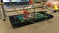
Here is the final soldered electronics including the resistors for the voltage divider, LCD connections, potentiometer, quick disconnect for the fan, and portable power source.
-
 Close up of Soldered Pins
 -
 Soldered LCD board for Wind Turbine
 -
 Portable Power Source for Wind Turbine Electronics
 -
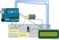 Circuit design from previous group. The only change that needed to be made was using lower ohm resistors and spacing out the pins that connect to the Arduino


int sensorpin = A0; // input pin for power (positive)
int sensorValue = 0; // variable to store the value coming from the sensor
double Vout; // voltage output
double i; // amps (current)
double p; // watts
double r1 = 7.5;
double r2 = 5.0;
double r = 12.5; // resistance value (ohms) 7.5k and 5k resistor
double c = 204.8; // constant value divider (1024 / 5) to get correct ratio. Analog pin reads up to 5v in 1024 increments.

#include <LiquidCrystal.h> // include the library code

LiquidCrystal lcd(12, 11, 8, 7, 4, 2); // numbers of the interface pins, more space between pins compared to last code

void setup() {
   lcd.begin(20, 4);  // sets up the LcD's number of columns and rows:
   Serial.begin(9600); // initialize serial communication at 9600 bits per second:
}

void loop() {

sensorValue = analogRead(A0);  // read the value from the sensor:

Vout=(sensorValue/c) * (r2/r); //vout = vin(Divided by c to scale down to 5v) * r2/(r1+r2)
i=Vout/r; // current = V/r
p=Vout*Vout/r; // power = (V^2)/r

lcd.clear();
lcd.setCursor(0, 0);
lcd.print("Amps= ");
lcd.print(i);
lcd.setCursor(0, 1);
lcd.print("Volts= ");
lcd.print(Vout);
lcd.setCursor(0, 2);
lcd.print("Watts= ");
lcd.print(p);
lcd.setCursor(0, 3);
lcd.print("SensorValue= ");
lcd.print(analogRead(A0));
delay(500);        // delay in between reads for stability
}
Utilization of Knowledge in Design
[edit | edit source]Technical and scientific knowledge
[edit | edit source]Knowledge of Physics, Computer Science, Circuit Design & electronics, soldering Acrylic handling, and CAD were all used during the design and construction of this project.
- Physics: All of the electronics were based off of ideas in Physics. The formula Current = Volts / Resistance is commonly known throughout the world of physics and is a core component to our project. Fluid Dynamics also helped us orient the turbine in the right direction to make sure the curvature of the blades assisted us in yielding the max power. These are all the formulas used in this project: :

- Computer Science: Arduino syntax and Integrated developer environment was used for the coding. Libraries for the Liquid Crystal Display had to be imported and when using the 'serial' function in Ardunio, digital pins 0 and 1 become unavailable.
- Circuit Design & electronics: A lot of research was done into the voltage divider to fully understand how to use it. Principles of positive connections and ground were heavily used in supplying power to the different components and making sure each piece was grounded correctly. The potentiometer for the contrast of the display involved knowledge of variable resistance to ensure it was wired correctly. Having knowledge of circuit design helped us even more when transferring from the breadboard to the compacted, soldered state. Knowing which wires to combine and splice into saved a lot of unneeded connections, such as joining the three 5 volts pins on the LCD display into one connection that went into a twist connection with the power for the potentiometer. The ground wires were also combined into one connection to limit the amount of busses and twist connectors needed to join everything.
- Soldering: Since we were working in pins very close to each other, soldering was difficult. Steady hands and patience proved useful. Very little solder needed to be used to minimize the chance of a short circuit. To ensure the most modular and maintainable design, each connection was soldered to a pin that was easily attached to the Ardunio. This way the Ardunio remained 'stock' and could be taken out easily to be used for other projects. Also, future teams could rewire the circuit without having to re-solder the connections. Each soldered joint was tested with a multimeter to ensure it was a good connection.
- Acrylic Handling: Using techniques such as scoring the acrylic to break off even pieces and placing masking tape around the cutouts to create clean cuts helped us when cutting the plexi-glass. Previous research into Acrylic cement allowed us to use the best possible 'glue' for the pieces to ensure the strongest bond. The Acrylic cement chemically bonded (melted) the pieces together to create one uniform piece. This allowed us to support the weight of the fan, both circle pieces made of acrylic, and the steel cutouts on 1 frame.
- CAD : Used to design the frame and shroud connectors of the wind turbine. Accurate dimensions helped us create an acceptable frame the first time.
Creativity, problem solving, and group decision-making
[edit | edit source]Creativity is very useful in this part of the design phase. The last group did an amazing job creating a wind turbine prototype but it had a few problems like being secured with duct tape. After brainstorming, we decided to design a shroud that will accommodate the fan by bolting it together. Also this idea was furthered by finding a way to make the shroud detachable on both sides of the fan. After brainstorming ideas, we concluded that a magnet-steel idea will work best. The magnet will be attached on the shroud and the steel on the plexi glass ring. This will make the wind turbine more portable and sleek.
One example of problem solving was changing the fan from an AC power to a DC power generator. This problem was crucial to solve because it is the heart of a wind turbine. Without the fan generating current, there won't be a functional wind turbine. It took research and weeks of works to finally convert the fan to DC power and rightfully so. Testing on the oscilloscope was done to confirm it works well.

Here's a Video of the fan connected to an oscilloscope

Another example of creativity and problem solving was deciding how to connect the fan to the circuit. We made a design matrix to choose between directly soldering it to the fan, using banana connectors, terminal connectors, alligator clips, or 9v battery connectors. Ultimately, we ended up using the 9v battery connectors because they allowed the fan to be swapped out easily in case it breaks. They also weren't as heavy or expensive as banana connectors, it was easier to connect than terminal connectors, and more secure than alligator clips. The 9v battery connectors allow for a tight, secure connection without any chance of short circuiting by brushing against other wires/metal and were the easiest of the group to disconnect and reconnect. They also happened to be the cheapest, which made our decision to use them very clear.
We had to make a few decisions based on the material to use for the final design. We made a decision matrix to decide as well as modify the circuit from the last group.
- Design a new shroud that will met the specification of the design assembly and also that will be adjustable and attachable on the Wind Turbine. The shroud will have magnets mounted on them that will enable easy testing whenever required. All the concepts we had were concept we came up with and we made decisions on which ones that will be implemented for this project.

Prior work in the field, standardization and reuse of designs (including reverse engineering and redesign)
[edit | edit source]Prior knowledge in soldering, knowing the basics and creating circuits, handling arduino and coding it, as well as knowing how to use some the tools used to cut and drill holes to build the structure is required to work in this project. Because this project continued work done by previous groups, the idea of having the whole structure portable was reused as well as a lot of other ideas and designs, too.
Modeling and/or Simulation
[edit | edit source]Just like the previous group, Fritzing, an open source software that allows users to build virtual circuits, circuit diagrams, and schematics, was used to create an electronic model of the circuit. A simulation of final design was done using a nine volts battery, and we were able to produce close six to seven volts of power.
Multi-Objective Design (DFX)
[edit | edit source]Performance, life cycle cost and value
[edit | edit source]Performance varies according to the purpose the wind turbine is used for. The performance will also be based on the purpose of the wind turbine. With an improved motor it can generate more power and due to the shroud design, it is safer also unlike the traditional wind turbine, which can be harmful to birds. The shroud design is a more cost effective approach because it generates more power so companies can presumable save more energy to disperse to consumers. The design is also cost efficient because it doesn't require the conventional huge blades that the regular wind turbine uses.
There is room for improvement in the design ranging from a better shroud, to fan, which will generate more power during the later stages of the product development. To maintain the best performance, a lot of testing has to be done to determine the best performance before it is mounted because once it is mounted, optimal performance will be expected thats why it has to be proven to be working normally under different conditions like rough wind, storm and some natural environmental changes.
The regular wind turbines have long blades and this makes them go really slow. When wind speed goes over 20mph, the blades stops otherwise they will go too fast and break but with the shroud protecting the blades, it allows it more room to spin, producing more power that would be saved and distributed to consumers.
Aesthetics and human factors
[edit | edit source]We tried to make it look better than the old model, which was just pieces of wood glued together and hold onto by duct tape. Usage of plexiglass did make it look much more beautiful than the wooden structure. Other than that, and the use of bolts and acrylic glue and make a hole in the stand, the design wasn't changed, just the material used to make it. In order to replace a shroud with a different shape we came up with a concept that allows a person to place the shroud and tighten it with two bolt around the fan. It was more elegant than using duct tape to connect the fan and other shrouds. The color of the shroud will still be black as it will less attracting animal (insects etc) that could presumable be attracted to bright colours.
We also made it very easy for users to turn it on and off (A switch on the battery holder), access the usb port for the Arduino to reprogram it, connect and disconnect different fans, adjust the contrast of the LCD screen, and swap shrouds from the front or the back of the turbine. It's rugged enough to withstand typical human abuse during operation (quadruple checked solder connections, thick bolts for the fan, enclosure for wires and arduino, thick plexi-glass won't shatter, splinter, rot, or warp due to dampness).
Implementation, verification, test and environmental sustainability
[edit | edit source]The plan for implementation is to first verify performance by running multiple testing on the wind turbine. This test is planned to be a final design verification, identifying any technical or coding issues' otherwise giving assurance that the circuit is working at it optimum best.
The next group responsible for this project will design a shroud on Solid Edge. This shroud will have exact specification as the ring plexiglass. The dimension can be found at "The Final Design" and they are called blueprints with ST6. After designing and printing the shroud, attached magnets along the diameter. After this, test the shroud and record your reading. Repeat the same for different shapes of shrouds and record you're reading accordingly.
Maintainability, reliability, and safety
[edit | edit source]The wind turbine thats we are designing is much smaller than the traditional wind turbines; thus, maintaining it would be easier and cost efficient. The cost of transporting a long blade (40-60 meters) is much but with the shroud design, it can be transported in segments and made to fit in small compartments. Due to the the nature of the wind turbine, visual blade inspections can be carried out regularly and in some cases regular surface cleaning may be necessary to maintain optimal performance; however, this will be an easier and cost effective process.
The reliability of a wind turbine is important for investors who have invested in this type of shroud because it will increase the cost per unit of electricity generated. However, it will count for nothing if the wind turbine breaks. Before the wind turbine is mounted out, a lot of testing has to be done with all the essential components to make sure they can withstand all the main requirements listed at the start of this report.
Safety is an important factor behind the shroud design. Conventional wind turbines are known to be unsafe for birds due to the size and also it has goes slow with a maximum sleep of 20mph. With the shroud design, the fan will be secure and wouldn't have to spin slow (speed of >20mp) thus, producing more energy.
Robustness, evolution, product improvement and retirement
[edit | edit source]A stronger material can be used to build the structure for the wind turbine rather than plexiglass. There is a lot for product improvement, from the material, to the fan and the shroud. Due to the design of the fan, the way it's made, it can't produce more than 10 volts. If it tries to go any further, it starts to fall apart from the center of the fan. The center of the fan becomes more loose everytime it passes 10 volts. Also, it is possible, and very probably necessary depending on the weight of the shroud, that some weight needs to be added to the base. The easier way we found was to add some weight inside the arduino box ( small piece of wood for example).