UTPA STEM/CBI Courses/Mechatronics/Basic Electronics
Course Title: MECE-4320 Mechatronics
Lecture Topic: Basic Electronics
Instructor: Horacio Vasquez
Institution: UTPA
Backwards Design
[edit | edit source]Course Objectives
- Primary Objectives- By the end of this challenge, students will be able to:
- Read a schematic and make basic electronic circuits using resistors and LEDs.
- Understand and use breadboards, power supplies, and digital multimeters (DMMs).
- Understand and use units in basic electronics
- Sub Objectives- The objectives will require that students be able to:
- Use breadboards and power supplies.
- Measure resistance, voltage, and current using a DMM.
- Connect and measure resistors in parallel and series.
- Apply Ohm’s Law.
- Understand and use LEDs.
- Understand and apply Kirchhoff voltage law.
- Compute power and energy consumption by resistors and LEDs.


- Difficulties- Students may have difficulty:
- Correctly using the correct relationships and units between voltage, current, and resistance.
- Correctly using breadboards, color code wiring, and power supplies to implement basic electronic circuits.
- Correctly using DMMs to measure current, voltage, and other parameters because not only they need to know the correct lead connections but also setting the knob of the DMM to the right place and range.
- Real-World Contexts- There are many ways that students can use this material in the real-world, such as:
- There are many applications that use basic electronic circuits including resistors and LEDs: traffic lights, flash lights, street lights, monitoring systems, video game systems, etc.

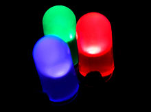
LEDs - Learning the mentioned concepts and acquiring hands-on experience in basic electronics are intended to be the first steps to encourage students to pursue a career in a STEM field, such as electronics, semiconductors, measurements and instrumentation, mechatronics, and control systems.
- There are many applications that use basic electronic circuits including resistors and LEDs: traffic lights, flash lights, street lights, monitoring systems, video game systems, etc.
Model of Knowledge
- Concept Map
- Electronic components
- Resistors, light emitting diodes (LEDs), and power supplies.
- Parallel and series connection of resistors.
- Units.
- Symbols and diagrams.
- Electronics Instruments
- Breadboards and DMMs.
- Measuring resistance, voltage, and current.
- Ohm’s Law
- Voltage, Current, and Resistance.
- LEDs
- Polarity, current limits, and connection requirements.
- Power consumption and energy utilization.
- Electronic components
- Content Priorities
- Enduring Understanding
- Resistors
- LEDs and their correct connections.
- Using a breadboard.
- Ohm’s Law.
- Important to Do and Know
- Correctly using a DMM
- Worth Being Familiar with
- Understanding power supplies.
- Computing power and energy consumption by resistors and LEDs.
- Kirchhoff voltage law.
Assessment of Learning
- Formative Assessment
- In Class (groups)
- Pre-test.
- Group activities:
- Adding resistors in series and parallel. Use Ohm’s law to determine expected currents and voltages in resistor circuits.
- Study LEDs and ways of connecting them.
- Compute power and energy consumption.
- Lab Work
- Using a breadboard.
- Create circuits, measure currents, and voltages.
- Validate Ohm’s law and Kirchhoff’s voltage law.
- Explain the results of the hands-on activities and the reasons why the system might not function properly.
- In Class (groups)
- Summative Assessment
- Conclusions and answers to handout questions.
- Solution to the Challenge.
- Post-test
Legacy Cycle
[edit | edit source]OBJECTIVE
- Goal - By the end of this challenge, students will be able to:
- Read a schematic and make basic electronic circuits using resistors and LEDs.
- Understand and use breadboards, power supplies, and digital multimeters (DMMs).
- Sub Objectives- The objectives will require that students be able to:
- Use breadboards and power supplies.
- Measure resistance, voltage, and current using a DMM.
- Connect and measure resistors in parallel and series.
- Apply Ohm’s Law.
- Understand and use LEDs.
- Understand and apply Kirchhoff voltage law.
- Compute power and energy consumption by resistors and LEDs.
THE CHALLENGE
You are working for a videogame company and they are going to release a new system. You supervisor wants you to inspect LED circuits that are malfunctioning. It is your job to get the circuit up and running in order to meet the deadline to release the system. The company is planning to sell millions of games and your future job and salary depend on executing such plan at perfection.
GENERATE IDEAS
Students are requested to brainstorm and write down ideas about the challenge, requirements to solve the challenge, importance of finding a solution, difficulties, and limitations.
MULTIPLE PERSPECTIVES The following link presents some information about LED applications: LED lights!

Common applications of LEDs: traffic lights, computers, and toys. Which other ones? Included information form different sources to demonstrate the importance of the challenge and engage students in solving it.
RESEARCH & REVISE
Present Lectures and handouts. Students need to study the lecturers and the handouts before doing the hands-on activity.
TEST YOUR METTLE
- i. Students do experiments (work in the lab to learn through hands-on activities).
- ii. Instructors ask questions in order for students to explain their experimental results and understanding of concepts.
- iii. Post-test.
- iv. Answer the questions in the handout.
GO PUBLIC
- i. Students demonstrate to the instructor and other students how their electronic circuits work.
- ii. Students turn in the results and conclusions, including possible solutions to the challenge.
- iii. Show pictures, videos, presentations.
Pre-Lesson Quiz
[edit | edit source]Knowledge Check 1
[edit | edit source]Read the user testing data and then indicate whether it is quantitative or qualitative by selecting the appropriate radio button. When you are finished making your selection, click the "Submit" button.
Knowledge Check 2
[edit | edit source]Read the user testing data and then indicate whether its severity by selecting the appropriate radio button. For the purposes of this exercise, you have already confirmed each item's veracity. When you are finished making your selection, click the "Submit" button.

