Power Generation/Steam Power/Part2
| Stage 1: Coal & Ash handling
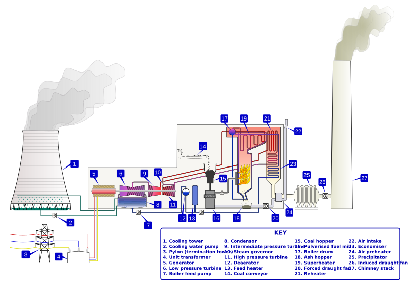
This stage is seen as the entrance and exit of fuel( coal )used. The initial handling treatment and storage of coal and the final handling and disposal of Ash.
Stage 2: Steam Generating Plant This stage is seen as the energy loss stage. The steam creation by heat accounts for the greater percentage of power station in-efficiency.
Stage 3 & 4: Steam turbine & Alternator/Generator This stage is seen as the energy conversion stage. The steam turbine converts steam energy to rotational mechanical energy, while the Alternator/Generator converts rotational mechanical energy into electrical energy.
Stage 5: Feed water & Cooling This stage is seen as the recycling stage. Steam used in boiler chamber is condensed back to water for re-use.
| |||||||||||||||||||||||||||||||||||||
| This schematic diagram must be properly understood. it is the basis upon which Steam power station designs are done. the individual power station complexity may differ slightly to the schematic and yet over and above that will use the same principle. | |||||||||||||||||||||||||||||||||||||

