
Lightweight Robot
Problem
[edit | edit source]Why does anyone want to make a robot? The answer is to do things for them. We decided to build a lightweight robot that may be able to address some of the needs of the everyday person who at any given time and for any given reason is just not able to get up. You may be too busy or you may just be too lazy; and our robot will be able to get what you need or get who you need.
Conceive
[edit | edit source]The most important detail about our robot was that it must be lightweight. We did not want a hulking noisy beast that would disrupt the regular flow of whichever setting it was used it. Also if the robot was too large or too heavy it could possibly damage the terrain it moved on and where it could go would be limited as well. Also, the smaller the robot the cheaper, and the easier to operate; in terms of coding and in terms of power supply. Keeping the robot lightweight, small and compact was the best option fiscally and logically. Next we wanted the robot's chassis to be as simple as possible, to allow for more efficient further growth. We also wanted the robot to be able to carry certain things on its back; such as the arduino/motor shield and other things such as notes or other small items. A flat top would be most conducive to this purpose. We wanted the robot to have the smallest amount of wheels as possible in order to keep coding and directionality less complex. However with only two wheels in the back balance could become an issue, so we thought maybe a non-motor controlled "nose" wheel in the front would be beneficial. Another of our goals was simplicity, so the least complex and most user friendly motor types would be the best. Servo motors fit this bill. In order for our robot to effectively be able to navigate its place of use, we had to give it certain technological upgrades. We would need the robot to be able to avoid obstacles, because it is not as if everything in a house or an office etc. always stays in one place. An obstacle may show up in a certain place one day where it wasnt before. For our robot to effectively avoid these obstacles, it would need an ultrasonic sensor to be able to locate the obstacles and the distance between them, then act accordingly. The robot would also need some way to direct itself, or follow directions that the user wouldnt have to get up to give. In this case, a reflectance sensor would be most useful. We could tape down white colored lines that would lead to various rooms.
Design
[edit | edit source]Chassis
The chassis was built with a light but sturdy and easy-to-cut wood acquired at home depot. We started with a 10.5 inch long, 8 inch wide plank of the wood. The wood was also approximately 1.5 inches deep. To make the two slots in the back for the wheels we cut 3.5 by 2 inch slots in the left and ride sides of the board; 2 inches from the extreme back of the board. Also a 2 inch wide nose was cut out at the front of the chassis. The board was narrowed down into the nose by cutting at a 30 degree angle from the sides approximately 3 inches down the length of the board. With our design there was space left at the top and bottom of the chassis for the motors and the arduino/motor shield. Also in the center of the board 6 inches from the back, there is a hole where all of our needed wires can come up through or go down through.
-
 Topside of finished chassis

Wheels
The wheels that we used were adapted from a toy race car and are about 2 inches long and 2 inches wide. They have a durable, smooth rubber tread.
-
 Base wheels

The servo motor shafts are attached to the gears in the wheel by screws. Two screws are used in all by each wheel. The nose wheel that we decided to use was adapted from an office chair, and screwed in to the bottom of the board using 4 screws approximately 1.5 inches from the front of the board and 3.5 inches from the sides.
-
 Nose wheel

Also, in order to balance out the wheels with the nose wheel we needed to add a small piece of square wood under the motors. They were fixed in with one screw and basically gave the base wheels some extra height so that the entire robot didnt move lopsidedly.
Motors
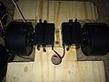
To move the robot we used two Parallax continuous rotation servo motors attached to the wheels in the manner previously stated.
-
 Parallax servo motors

Some key features of the servos are:
Bidirectional continuous rotation
0 to 50 RPM, with linear response to PWM for easy ramping
Accepts four mounting screws
Easy to interface with any Parallax microcontroller or PWM-capable device
Very easy to control with PBASIC's or SX/B's PULSOUT commands
Weighs only 1.5 oz (42.5 g)
Some other details are:
Power requirements: 4 to 6 VDC* , 15 -200 mA
Communication: Pulse-width modulation
Dimensions: 2.2 x 0.8 x 1.6 in (55.8x 19 x 406 mm) excluding servo horn
Operating temp range: +14 to +122 °F (-10 to +50 °C)
Torque: 38 oz-in @ 6 V
To attach the motors to the chassis we employed the use of zipties. We laid the servo motors on their sides and then drilled a small hole slightly above and below the servo motors. We then used one ziptie each to fasten the servo motors to their place on the chassis. We then cut off as much of the exposed tips as we could so as to not have unnecessary clutter.
-
 Ziptie set up

The servo motors connect easily to the Adafruit motor shield through pre-designated servo pins on the shield. We created a basic code that shows a brief glimpse of all ranges of motion with the servo motors:
-
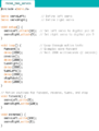 Code part 1
 -
 Code part 2


This code dictates that the robot go forward for a short amount of time, then reverse, then turn left, then turn right, then stop. And repeat.
Sensors
In the end we will be making use of two sensors, but currently we have only begun incorporating the ultrasonic sensor. The reflectance sensor will come later. The ultrasonic sensor is a HC-SR04 model.
-
 HC-SR04

Some features of the sensor are:
Power Supply :+5V DC
Quiescent Current : <2mA
Working Current: 15mA
Effectual Angle: <15°
Ranging Distance : 2cm – 400 cm/1" - 13ft
Resolution : 0.3 cm
Measuring Angle: 30 degree
Trigger Input Pulse width: 10uS
Dimension: 45mm x 20mm x 15mm
This model has 4 wires coming out of it, an echo, a trig, a 5V power wire and a ground. The echo and trig wires went to pins 2 and 3 on one side of the arduino while the power and ground wires went to their corresponding names on the opposite side. However these pins were not open for use on the motorshield. We had to solder open pins onto pins 2,3, 5V and ground. Once soldered, we connected the sensor to the motorshield with careful wiring.
-
 Sensor wire set up

In order to test the sensor, we compiled a basic code that dictated a LED start lit. When the sensor senses an obstruction, the light would turn off. Otherwise the light would stay lit:
-
 Ultrasonic sensor test code

A code that successfully incorporates the ultrasonic sensor with the motor movements is still in progress.
Implement
[edit | edit source]Operate
[edit | edit source]Demo
[edit | edit source]Next Steps
[edit | edit source]The next step in our project is the completion of the object avoidance code utilizing both the ultrasonic sensor and the servo motors. Once this code is complete our robot will be able to avoid objects which is imperative for its purpose. After that we will begin incorporating the reflectance sensor array so that the robot will be able to follow preset directions in the form of white tape. Once its navigation upgrades have been made, the next steps we would take would be optimizing its ability to carry things; which may mean some changes for the chassis. We will also work on how we could operate it and maybe turn it on or off wirelessly .