
Helicopter/Howard Community College/Fall2012/p3-504-drv


Electronic Sections Expected
[edit | edit source]Problem Statement
[edit | edit source]Build a structure that balances the slope of the Quadcopter PID
Team Members
[edit | edit source]Summary
[edit | edit source]During week 0, we picked our project and got assigned to various groups. It came out Quadcopter PID team was filled with Ryan, Daniel and Vincent.
During week 1, We decided to research about how the quadcopter PID works in general. We looked for the materials that last project group left. We got the propellers, wooden boards, PVC pipes, and the Arduino Mega. We got the serial chart worked with the Arduino, and we decided to create the general structure soon.
During week 2, we began to draw up new plans for a different PID testing system that would use a stand that would suspend our balance board with the propellers and PID. We designed the stand and balance board setup using the free student version of Autodesk Inventor.
Poster
[edit | edit source]

Credit to p1-504-anwk team
Story
[edit | edit source]We basically wanted to find out what the last team who tried to get this project ongoing. Daniel tried to find out how the Arduino and the accelerameter worked. Vincent and Ryan tried to find out how the gimbal joint and the balance board works based on the graphic that last team project created.
Arduino Codes
[edit | edit source][_setup_]
port=COM3
baudrate=57600
width=800
height=201
background_color = white
grid_h_origin = 100
grid_h_step = 10
grid_h_color = #EEE
grid_h_origin_color = #CCC
grid_v_origin = 0
grid_v_step = 10
grid_v_color = #EEE
grid_v_origin_color = transparent
[_default_]
min=-1
max=1
[interval]
color=transparent
min=0
max=100000
[RxAcc]
color=cyan
dash = 1
[RxEst]
color=blue
[RyAcc]
color=magenta
dash = 1
[RyEst]
color=red
[RzAcc]
color=lime
dash = 1
[RzEst]
color=green
This is the code that is used in SerialChart that finds about the balance based on the accelerameter We need to find out how this code actually works. This code seems like it's just for the program(SerialChart).
Decision List
[edit | edit source]
Making General Structure of Quadcopter PID
[edit | edit source]-
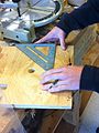 Calculating the length and width of the base
 -
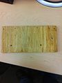 After Calculating the length and width of the base, we cut the large wooden board, and here's the base for the structure!
 -
 Hold the base structure and long wood as 90 degrees and nail through it.
 -
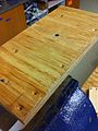 Here's the result.
 -
 Now we add the thin wood on the long wood and nail once at the left
 -
 To make sure the thin wood doesn't come out easily, we nailed it once more at the right


Material List
[edit | edit source]| Product Name | Description | Quantity | Price |
|---|---|---|---|
| Traxxas Front & Rear Half Shaft | TRA5151 | 2 | $7.44 |
| Hacker A10-13L Brushless motors | These are strong, despite their weight and size. | 4 | ~$54.00 |
| Thunderbird 9 ESC | Thunderbird 9 | 4 | $29.95 |
| Arduino Mega | Mega | 1 | $58.95 |
| Jumper Wires Premium 12" M/M Pack of 10 | Male to male | 2 | $4.50 |
| Breadboard Small Self-Adhesive | 5x5 pins or more | 1 | $5.95 |
| 5 DOF gyroscopic sensor | Allows for input of X, Y, and Z accel, as well as X and Y rates. | 1 | ~$49.95 |
Software List
[edit | edit source]Time
[edit | edit source]15 hours
Tutorials
[edit | edit source]None at the moment
Next Steps
[edit | edit source]About the arduino
[edit | edit source]We couldn't really find anything about the arduino. Finding similar programs and softwares were easy;however, those needs additional equipments that will cost money, so we do not recommend them. For the next group, they will need to first try the strarlino code that is above listed, and make sure the accelerometer works with arduino, and then somehow figure out how this can be applied to Quadcopter PID.
About the structure
[edit | edit source]Whether the next group will use the structure that we made or not depends on their decision. If they decided to use our structure, they need to look at our decision matrix about the gimbal joint, and put the gimbal join with the material we have left and follow the structure, which is located above.
Conclusion
[edit | edit source]- Make sure you understand arduino and accelerometer before beginning this project. (For codewise, it doesn't have to be everybody in the group, but basic understanding will still help them)
- Research how arduino can be applied to the structure
- Attach the gimbal joint or somehow make another design of the Quadcopter PID
- Find out how to connect propellers with arduino and try to run them.
- Also, figure out where arduino will be put on the structure if using the same structure of the previous group.