
Engineering Projects/StrandBeest/Howard Community College/fall2012/p3 501 DP
Electronic Sections Expected
[edit | edit source]Problem Statement
[edit | edit source]To construct a standard hand powered StrandBeest made of PVC piping and wood that walks on the ground.
Team Members
[edit | edit source]Summary
[edit | edit source]Through research we found no success from previous groups so we started this project mostly from scratch. We designed and fabricated our strandbeest using proper lengths and proportions as supplied by the original designer of the strandbeest. We accomplished a mechanically working strandbeest, however there are a few aspects that can still be improved upon if a group were to pick this project up.
Poster
[edit | edit source]http://commons.wikimedia.org/wiki/File:Kjgkhbebertb.png
Story
[edit | edit source]Week One
[edit | edit source]
Week one was primarily spent researching previous projects and determining what we wanted to actually achieve through this project. We found that the original man who created the strandbeest has created a list of proper proportions, which he refers to as his "holy numbers", these can be referenced in the thumbnail on the side. We also found that there were several groups at HCC who had started this project, but the majority lacked proper documentation or just had not completed it. We also found that there were some left over parts we might be able to use to complete our strandbeest, however ultimately we decided that those parts would not fit ours efficiently.
Some of the preliminary materials we considered using for this project were:
- PVC
- Wood
- K'nex
- CPVC

We ultimately chose a combination of PVC and particle board for our project, and the decision matrix for this can be referenced below. Beyond researching the materials and past projects involving the strandbeest, we needed to first establish a good understanding of how the strandbeest actually operates mechanically. We found this video, which is the primary model for how we designed and understood how to build and create our own strandbeest.
We also found that Theo uses a material which he refers to as "electrical tubing" similar to PVC except it is lighter and more malleable than traditional PVC tubing however we chose to use PVC tubing as our material simply because it is easy to cut, it comes in various sizes, it's cheap and it's in any local hardware store.
In order to get the ball rolling early so we didn't get behind, we fabricated an early prototype for our crankshaft. We wanted to do this early, as we had found that the primarily downfall for most groups who had worked on this project was a faulty or weak crankshaft. We built ours out of 1/2" PVC. We also found that the angles for the leg extensions on the crankshaft should sum to 360 degrees. So if you have 3 legs on each side, each leg extension should be 120 degrees from the previous.
Week Two
[edit | edit source]
We spent week two crunching numbers and converting the proper proportions for our own design. We decided that it would be best to get organized and layout our design before we started to fabricate anything. Also while we have the proper proportions to build the leg, there are two major designs you can use. One is a triangle bridge design, that acts as triangle shaped trusses between the legs, and the rectangle design that is a simple rectangular frame that connects the legs. For simplicities sake, we chose the rectangular design.
We also came to a consensus on our materials for design this week. We will use particleboard for the legs due to it's strength and cost, and pvc also due to it's strength and cost.
The conversion of the leg proportions can be seen to the right.
Week Three & Four
[edit | edit source]Week three and four most of our time was directed at fabrication and building the strandbeest. Since we had created our measurements and sketches, along with a material list in the previous weeks we were able to just power through the fabrication process. We utilized a circular saw, a table saw and a drill to build the strandbeest.


We had our original design set so that ever side of the leg was connected through singular pieces, however in a last minute decision we chose to utilize two triangles to simplify our design and provide more strength.
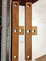
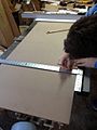
Before we did any cutting we made sure to label and properly draw out all the pieces correctly.
We met at Derek's house where we have access to all our tools so we could begin cutting out all the pieces. We feel it wise to only start with enough to make one set of legs to see how they work as a prototype. From then on we will make any adjustments and make all the rest. In total we plan on using J=6 K=6 C=12 F=12 EDB and GHI will be triangles and will only need 6 of each. Making that a total of 42 pieces all made out of particle board. They will be jointed together using tubes of 1/2" PVC.
After making the prototype leg and it seemed to work perfectly so we we moved onto cutting out the rest of the pieces without having to change our design.
We also began drilling holes in the segments for the joints to fit through. All the joint we cut using a table saw and all holes were drilled using a 7/8" paddle bit and a drill. It would be very useful to any future groups to use a drill press simply because it is more accurate and will be MUCH FASTER but we do with what we got. We eventually finished cutting all the pieces now we just need to finish drilling all the holes which so far has been the most time consuming portion of the project.
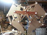
We finished drilling all the holes now we begin assembling the StrandBeest, we found it best to hang the frame from the ceiling that way the legs are free from hitting the ground. We also off set the three sections of the crank shaft by 120 degrees this way we get a full circle of motion between the legs. For future groups if you are not sure what to offset your crank to heres how. How many sets of legs will you have? In our case we have 3, now divide 360/3 which is 120 degrees, If you had 4 sets of legs you would divide 360/4 to get 90 degrees. Just as long as you have a full circle of motion between each set.
The final product can be seen in working order here, through this video.
- Strandbeest Fabrication and Design Gallery
-
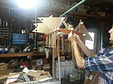
 Assembling the prototype leg
 -
 The Strandbeest Frame
 -
 Assembling the prototype leg, 2
 -
 Cutting and drawing out the legs
 -
 Cutting the legs using a table saw
 -
 Cutting pieces
 -
 Final parts quantity, pre-fabrication
 -
 Glued and drying crankshaft
 -
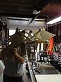
 Beginning fabricating the final strandbeest
 -
 Fabricating the strandbeest using our nifty makeshift lift
 -
 Isometric view of completed strandbeest
 -
 Side-view of completed strandbeest
 -
 Underside of completed strandbeest
 -

-


The final product can be seen in working order here, through this video.
Decision List
[edit | edit source]| Criteria | K'nex/Legos | Wood | PVC/Particle Board |
|---|---|---|---|
| Cost | - | + | + |
| Stability | S | S | S |
| Strength | - | + | + |
| Weight | + | - | - |
| Ease | + | - | + |
| Total | 0 | 0 | 1 |
Material List
[edit | edit source]All our materials were obtained from Home Depot with the exception of a few scrap wood pieces we had to make the frame.
| Item | Quantity | Price (each $) | Link |
|---|---|---|---|
| 1/4" Particle Board (2' x 4') | 5 | 5.97 | Link |
| 1/2" Standard PVC (10') | 4 | 2.87 | Link |
| 1/2" PVC Cap | 60 | 0.36 | Link |
| 2x4x8 Lumber | 1 | 3.57 | Link |
| PVC Cement | 1 | 7.48 | Link |
Software List
[edit | edit source]No software was used in the making of this project.
Tutorials
[edit | edit source]Mechanics of the Strandbeest Design Explained:
Next Steps
[edit | edit source]While we were able to accomplish some key aspects of this project, we left several parts of our goal incomplete due to certain constraints.
The core mechanics of the design we fabricated are solid. However if a team were to pick this project up the should focus on improving upon what we already have. The key features that one should focus on for the next project are reducing the friction between the joints; Reducing the lateral moving of the legs across the frame; and adding proper feet to add more stability for ground walking. We will go into explanations and ideas for each of these topics below.
Reducing the friction between joints:
The joints between the leg pieces are fairly smooth, however they can and should be reduced to minimal friction if possible. The easiest way to do this is to find a powdered lubricant to place in between the joints to allow more free movement. This would reduce the friction and reduce the amount of work needed to move or "power" the strandbeest. A good idea to use for this is graphite, which is cheap and can be found at the local hardware store. An example can be found here.
Reducing the lateral moving of the legs across the frame:
Through our design the rigidness of the legs rely on the spacing between the crankshaft. However there is still some inner movement between the legs themselves as well as between the legs and the crankshaft frame. To reduce lateral movement between the legs and the frame, one would need something to act as a barrier between the legs and the crank frame. The best and most practical way to do this is to use something like this and place it in between the legs to hold them rigid.
Adding proper feet to add more stability for ground walking.
We ran out of time, so our final design has bare triangle points for the feet. However these provide little to no traction and reduce the overall stability of the strandbeest. To counter this the next group will need to utilize a "foot" like design and retro-fit it onto the legs. We already drilled holes on the bottom of the legs to allow for quick and easy retro-fitting. We suggest using rubber or some lightweight but friction increasing material for the feet.
In addition to adding feet, it would be possible for the next group to essentially duplicate the design of the first one, and retro-fit it onto the existing strandbeest. With the proper workmanship one could seamlessly double the length of the strandbeest, allowing more stability and balance throughout the structure. One thing to consider with this idea however would be the integrity of the crankshaft. Before one should think about extending the strandbeest, you must make sure the crankshaft is strong enough to withstand the extra force.
Going Further
One should also consider the addition of a small motor or turbine to power the crankshaft, this would make the strandbeest a free walking structure. I cannot go much into details regarding this as this was not the focus of our project, however it would be a nice and welcomed addition to the project.