
Engineering Projects/StrandBeest/Howard Community College/fall2012/p3-550-ocm
Problem Statement
[edit | edit source]Build and design a walking strand beast. A walking mechanical machine.
Look through the different designs, formulate a way to fabricate the required parts and build it.
Team Members
[edit | edit source]Summary
[edit | edit source]In the first week of this project we worked on making crank shafts from different materials. We are making a crank shaft from steel and bolts and We are also working on a legos crank shaft. Previous teams have been unsuccessful in making a working crankshaft. After week one we have made one crankshaft that we believe will work. We are moving forward to begin designing and building the legs and body.
Poster
[edit | edit source]
Story
[edit | edit source]Starting out, we had a dilemma, to use the previous groups Lego crank, or redo the work of custom building a crank, such that our design is conformed to the dimensions, or "holey numbers" configured by Theo Jansen as seen here. Currently we are making the new crank out of a different material such that it did not have the bending problem of the previous model.
-
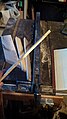
 Old bent crank
 -
 Marking where to drill the holes with a punch, denting the metal
 -
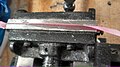
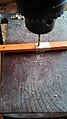
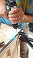 Drilling the holes
 -
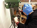 We switched to using the drill press to make more precise holes


After we finished cutting out each part, we assembled the crank. We now need to set the correct angles for each leg
-
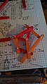
 Cutt up and drilled tabs for the shaft
 -
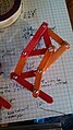
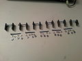 All of the parts for the crankshaft
 -
 The fully assembled crank, though the angles need to be measured precisely and secured with lock tight


After we add the finishing touches to the crank and body of the StrandBeast, we will start designing the legs.
Each of the 3 team members will independently conceptualize their own ideas for the legs of the mechanism over the weekend.
Other electronic designs can be seen by clickinghttp
here or here
The design that is closest to the design that we are building can be seen here
Progress of work with the Lego's.
-
 It is a propeller which we attached with the crank shaft to spin it.
 -
 These are some of the parts including Lego's bearing.
 -
 This picture shows the Lego bearing are attached with the leg of crank shaft. It will help to mobilize the legs of strand beast easily.


These bearings are very useful because we can attach the legs on it easily. we made four legs from the legos, and attached them together at 120 degrees, and made a complete crank shaft. It can be seen below in the picture. After making the central crank shaft we made a rectangular frame for the crank shaft. For the frame we took two 6.50 cm bares which had eleven holes with the diameter of 4.80 mm. we put the crank-shaft's axle in the middle hole. After that we measured the length of crank shaft which is approximately 42 cm, and we took two plastic rods with the length of 45 cm. From the ends of these plastic rods we turned them down to 4.80 mm so they can fit in the holes of 6.50 cm long bars.
-
 This is a complete central crank shaft with four legs.
 -
 All pieces of crank shaft.


At the end we just put all the pieces together. Now it is a complete crank shaft, and it can be spun easily.
-
 This is a complete crank shaft made of legos.

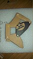
Progress of work with the wood leg. Tips and tricks are described in the image description.
-
 A drawing of the initial design of the wooden leg, turned out to be wrong.
 -
 An idea for a joint in which the middle piece can pivot through the full 360 degrees
 -
 The corrected schematic, with part quantity and dimensions included. the joint no longer needed.
 -
 The cardboard model finished and pinned.
 -
 Cutting out the triangular bits of the incorrect cardboard leg model.
 -
 Measuring and pinning each of the joints
 -
 All of the supplies I utilized for making the cardboard leg... minus my hands, those were kind of important.
 -
 Stuck washers to some electrical tape in order to press them flat to remove any inconsistencies from drilling them out.
 -
 pressing the washers on the tape
 -
 Using the drill press to punch out the washers
 -
 A few examples of failed attempts at drilling out washers.
 -
 First, I used a hand drill for the job, but it turned out to be too irregular.
 -
 When/if using the hand drill, always keep it on setting one, setting two just shreds the aluminum.
 -
 The first two successful washers made
 -
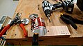 All of the tools for making the washers.


Continued work with the wooden parts. We decided for the sake of time not to use the aluminum can washers, punching out hundreds of them would prove time consuming.
-
 The failed slab, side view
 -
 The front view of the failed slab, showing the variance in width
 -
 The piece of wood which I found that fits the correct dimensions, a resource I did not know I had till I went looking for it
 -
 The first mark to be drilled, turned out to be too close to the edge of the stick
 -
 A correction of the first point such that the wood would not splinter
 -
 Taking the measurement of the second hole with my vernier calipers
 -
 IMPORTANT: Stack the sticks to drill multiple at once, and wrap them in masking tape to ensure clean holes and prevent shifting of the sticks which will result in inaccurate measurements.
 -
 progress
 -
 more done
 -
 Fin!
Fin! -
 finished piece, pivoted to one limit of movement
 -
 finished piece, pivoted to the other limit of movement


Some useful videos found here:
http://www.youtube.com/watch?v=tkV7Bym_qiU
http://www.youtube.com/watch?v=CufN43By79s&feature=em-share_video_user
A successful toy model from kickstarter found >>here<<
A funny hamster powered strandbeest: http://www.youtube.com/watch?v=A3iP0NGDDao
Decision List
[edit | edit source]List all formal decisions made with links to their documentation such as a decision tree or decision matrix.
Material List
[edit | edit source]Materials- A 3 foot X 1/8 inch by 2/3" inch welded steel bar was purchased at Lowes at a cost of $3.57 2-packages of 4-40 1 1/4 inch bolts with nuts, 10 pieces/each, each package. At a cost of $1.18 each. Various parts from a previous project.
A material needs to be determined for the legs and body of the strandbeest.
For each leg: 7 popsicle sticks
2 long screws of undetermined length ~12mm
2 screws 2mm shorter ~10mm
2 screws 2mm shorter ~8mm
14 washers? presuming washers are used
2 triangles built to specs
6 locking nuts/ 12 regular nuts
Software List
[edit | edit source]One of the team member used SAI paint tool to render some of the conceptual designs but other than that, there was no software used in this project short of a calculator.
Time
[edit | edit source]59 hours
Tutorials
[edit | edit source]All projects create new tutorials of technical details future participants are going to want to know. They are going to be separate pages that are linked to here.
Next Steps
[edit | edit source]The next steps to this project are to complete the prototype and begin working on methods to reduce the friction in the legs so that the beest can walk. Also, testing using a rivot gun to assemble the legs. The design worked on during this project, has 6 sets of legs. After assembling 1 set to the frame and crakshaft it was determined that 6 sets would have too much resistance. A design needs to be created that minimizes friction in the legs. Also another area that could be worked on is a design and method for a one wire design for the crankshaft. A method for bending a small steel wire in a precise manner to create a sturdy and stable crankshaft.