Engineering Projects/HoverCraft/Howard Community College/Fall2012/p1501east
Problem Statement
[edit | edit source]To fabricate and test hovercraft designs, specifically comparing results using a "classic" hovercraft (air cushion) with a hovercraft utilizing vertical take off and landing through prototyping. To develop a means of forward thrust and steering that is controlled remotely.
Team Members
[edit | edit source]Summary
[edit | edit source]Previous teams that have worked on this project have approached it with the assumption that a "hovercraft" is one that utilizes an air cushion underneath the body to enable hovering mobility. The body of the hovercraft is floating on a cushion of air, but in reality a portion of the craft is still in contact with the ground (the cushion). This project will attempt to build a working hovercraft, starting from the design concept of a craft that does not use an air cushion. The vehicle as a whole will float, utilizing a form of vertical take off and landing like a helicopter. Work will start with building a prototype of a three prop hovercraft that does not utilize an air cushion. If that design shows promise (it takes off), the design will be refined. If it does not, an air cushion will be added to see if that will successfully float the body of the craft. If that proves fruitful, the design will be refined, but a second prototype will be built using additional fans to try to achieve vertical lift.
Story
[edit | edit source]The team met and decided on a problem statement. The team decided to build a VTOL(Vertical Take-Off and Landing) type hovercraft in which fans were used to make it float. Most hovercrafts use their fans to fill a bag of air which they then float on, but this project started from the design concept of a hovercraft without the cushion. The original intent was to use computer cooling fans to provide lift, but the team had access to model helicopter motors, so it was decided to use those instead.
Initial design procedure:
1. Produce three fan prototype with no air cushion and test the design.
   -Build a body with ducts for three fans
   -Install and wire the three fans and use either a battery or a variable power source that will transform AC into the needed DC voltage and current.
   -Initial test with it wired, then simulate the load of a battery and control fan rig
   -If this works (produces necessary lift), refine the design, if it doesn’t go to step 2:
2. Produce a variant that has an air cushion on the bottom to maximize use of downward thrust.
   -Use the same body
   -Attach a cushion to the bottom, I am thinking clear plastic tarp or mylar balloon for the material.  Mylar would be lighter, but probably less durable.
   -Test first with it just wired, then simulate battery and control mechanism load.
   -If test data seems positive, refine. Ideally the final design will not use an air-cushion, so move on to step 3:
3. Produce a six fan variant
   -Build a new body, as by this point the other may be damaged, and retro-fitting it may reduce structural integrity
   -Re-wire the system for six fans
   -Same testing parameters as above.
   -Refine.


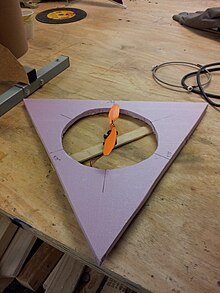
A small-scale prototype of the craft was built to gain insight into the project's scale and construction method. This prototype revealed that the scale of the craft was going to be much larger than initially suspected in order to accomodate the span of the fan propellers. The main craft body was constructed out of 0.75" thick pink insulation foam. It was made from four triangular pieces that formed a 46" equilateral triangle, and was two sheets thick (1.5"). 8.5" holes were cut at the three corners as ducts for three fans, and the top edges of the craft body were beveled to decrease drag on take-off.
The prototype was used to develop the structure of the fan mounts. The fan mounts needed to be structurally stable enough that they would not break in the event of a crash, which was likely during testing, but also needed to have enough give to dampen vibration while they were running. Excessive vibration in the propellers would lead to unbalanced lift when the craft takes off. A system was designed to mount the fan motors 1" above the top surface of the craft using hand cut copper pipe stand offs. The fabrication of copper stand offs that were precise enough to serve this purpose proved unsuccessful. Instead of mounting the fans on stand-offs, two layers of insulation form were adhered in 1.5" strips to the bottom outside edges of the craft to allow room for the fans to be mounted directly to the top surface of the craft body. The fans were mounted on a plywood crossbar, and plywood braces were cut to support a bolt that ran through the foam body of the craft. This mounting design change was also applied to the full size hovercraft body.


In order to proceed with a test of the prototype, a means of powering the fan was needed. The voltage source was a modified Ac adapter from a laptop, which was within the voltage and current constraints outlined in the specifications of the Zagi 5 electronic speed controller. The Zagi 5 would control the current output to the brushless motor. The power leads from the Zagi 5 were then attached to the motor mounted on the prototype. The ESC did not provide power to the motor. When the motor was connected to the ESC power leads for the RF receiver, the fan started to spin, but after a second or two it started to make a grinding noise. The ESC power leads were not able to supply power to the motor because there was no means of providing it with an initialization signal.
This was the point at which the project cycle was complete. Unfortunately, we were not able to produce a working prototype in the time allotted. Due to the time constraint, we had attempted to build the full scale craft while fabricating the prototype. In retrospect, it would have been more effective to focus on the production of the prototype before starting on a full-size model.
Decision List
[edit | edit source]Material List
[edit | edit source]- 3/4in insulated foam
- Brushed motors for fans
- Fan blades
- AC adapter
- Wire
- Plastic Sheet
- Plywood for fan mounts
- Zagi 5 Brushless Electronic Speed Controller
- Thunderbird 9 Electronic Speed Controller

Software List
[edit | edit source]- Arduino v1.0.1
Time
[edit | edit source]30 Hours
Tutorials
[edit | edit source]Tutorial on producing a Western Union splice is posted on Youtube.
Next Steps
[edit | edit source]The next steps for this project would be as follows:
1. Locate or write an arduino sketch that will provide an initialization signal to the electronic speed controller. Without this signal the ESC can not provide power to the motor.
2. Test the motor currently being used to determine if it has a high enough lift to weight ratio to be effective.
3. If the lift to weight ratio is insufficient, switch to a brushless motor with a higher ratio and test again.
4. If the more powerful motor is ineffective, attach a hovercraft skirt and test again.
5. If either of these motors proves effective, move to the full scale craft with three fans. Modify the arduino sketch to include all three ESCs.

