
Engineering Projects/ComboLockPick/Howard Community College/Fall2012/p1-502-cmsb/switchamp
Switching Amplifier
[edit | edit source]SAFETY WARNING – ELECTRIC SHOCK HAZARD
[edit | edit source]- The 120 volt ac terminals of the solenoid and driver relay have not been properly insulted. They were connected temporarily for test purposes only. Make certain that further testing of the circuit is done either with a full awareness of short circuit and electric shock risks (and taking precautions to avoid them) or that all 120 VAC terminals have been properly insulated before energizing with line voltage!
Developmental Versions:
[edit | edit source]1) A microwave oven control board modified to drive the solenoid.
- Advantages:
- simple and quick to implement,
- Disadvantages:
- unnecessarily bulky and unsightly.
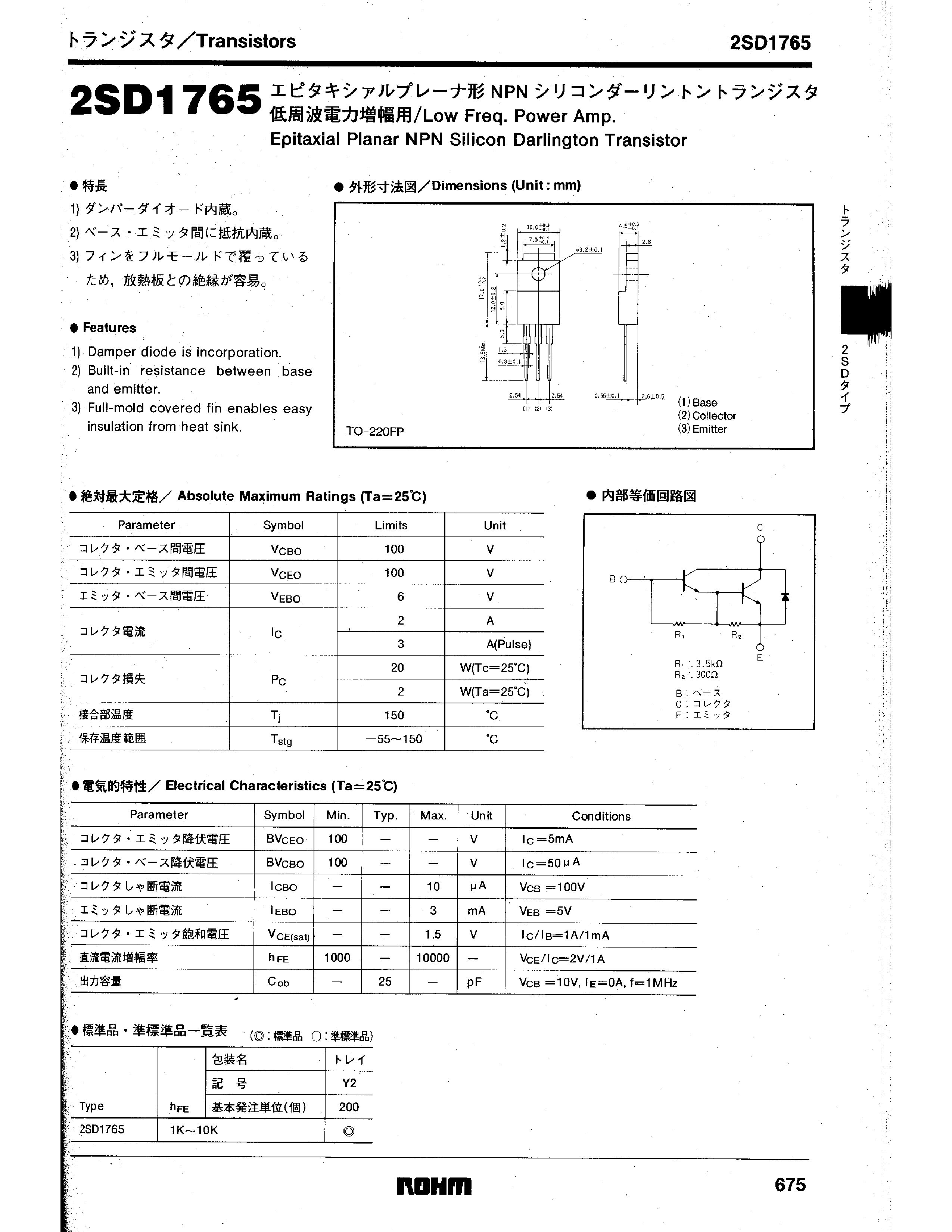
2) A Finder relay type 40.31.9.024 driven by a 2SD1765 transistor salvaged from surplus equipment at HCC
- Advantages:
- used only 3 parts, so much more compact and light weight
- lends itself to convenient mounting on the final lockpick foundation
- Disadvantages:
- unlike version 1, it required an external power supply of 24 volts dc, meaning it could not be driven by either the arduino power supply or the computer usb port
- the small, fragile terminals on the 40.31 relay posed a risk of breaking off or bending, which could short out the 110 volt ac relay supply, or expose those terminals to human contact, posing a serious safety hazard.
- Several options were considered for dealing with the ac safety problem of version 2, including:
- soldering all parts together, encapsulating the entire circuit in electrical tape, and securing to the lockpick frame (perhaps with yet more electrical tape)
- making a custom printed circuit board (PCB) for mounting the finder 40.31, because the 40.31 was designed to be mounted on a PCB and doing so would overcome many of the drawbacks of version 2
- soldering all parts together, putting them in a small container such as a can or box made of wood, plastic, or metal, and encasing the entire circuit in an electrically insulating potting agent, such as epoxy, wax, or liquid electrical tape, (as in some transformers or telephone parts) and mounting the container on the machine frame
- salvaging a relay with terminals that are more mechanically secure and easily insulated
- The eventual decision was to salvage a relay with more secure ac out terminals because such a relay, the omron G5G-1A was available, for free, on the microwave oven circuit board used in version 1, above. This resulted in the final version, below.
Final Version:
[edit | edit source]- The final version of the switching amplifier consists of an omron G5G-1A relay driven by a 2SD1765 transistor, which is in turn driven by the arduino through a 22,000 ohmresistor to limit current. Due to the voltage requirements of the relay coil, and the drop in the transistor, 24.7 volts should be supplied between the emitter terminal of the transistor (-) and the relay coil terminal not attached to the transistor (+). Though 24.7 would supply exactly the 24 volts required by the coil and the transistor junction voltage drop of .7 volts, variations from the ideal value to as high as 25.2 (a common PS voltage) or as low as 23 volts should not cause problems. The emitter terminal should also connect to arduino ground, and the arduino control pin should be connected to the free end of the 22k resistor.
Relay:
[edit | edit source]- The omron G5G-1A relay (datasheet here) was chosen for its ac output terminals, which are more secure than those on the finder 40.31.9.024 relay that it replaced. The coil current and pull in voltage characteristics are slightly different, so if future teams decide to use the 40.31 instead, they should consider this fact and compensate. Both relay types have coils rated for 24 volts D.C. Experiments have shown they pull in and power the solenoid considerably below that, in the 14-17 volt range, giving some flexibility in choice of power supply. However, it should be considered that at reduced voltages, the magneto motive force developed by the magnet coil is reduced, which reduces the flux in the magnetic circuit. This, in turn, reduces the force on the armature, and by extension the pressure on the electrical contacts. As pressure of the electrical contacts is reduced, the resistance of those contacts is increased. Increased contact resistance causes more heat to be developed at the switch points for a given current, in accordance with Ohms' Law. This extra heat can cause premature failure, or destruction, of the contacts, shortening the useful life of the relay. For this reason, operation of the circuit below 23 volts should be avoided, though at the switched currents involved it is probably not a serious or immediate threat. Our team used a variety of external adjustable power supplies to feed the relay/switch amp combination, in addition to the arduino and solenoid power supplies. If future teams wish to use the wall wart power supply that drives the arduino to also power the relay, they might want to consider selecting a relay with a 12 volt coil to replace the G5G-1A. They might also wish to experiment with this circuit for operating relays below their rated coil voltages.
Driver Transistor:
[edit | edit source]- The driver transistor, a 2SD1765 epitaxialsilicondarlington pair transistor, was chosen based on its presence on a surplus circuit board and a physical appearance which vaguely suggested it should be capable of passing substantial current or take substantial voltages. This initial belief was confirmed by the datasheet , which, among other characteristics, shows a maximum collector-emitter voltage of 100, a maximum average collector current of 2 Amperes, and a maximum average power dissipation capability of 2 [Watts]. Efforts to locate suppliers of new 2SD1765’s have thus far been unsuccessful, so if the existing unit were to be destroyed, it may become necessary to replace it with a transistor of a different type. A 2N2222 is suggested as a design starting point on the basis of being both readily available and possessing ratings suitable for the given relays. CircuitLab would be an excellent tool to assist with any such design process attempt.
Current Limiting Resistor:
[edit | edit source]- To determine the proper value of the limiting resistor, an arduino output voltage of 5.0 DC was assumed, and the base current of the relay driving transistor was measured with a digital multimeter while varying the input voltage to it, with no limiting resistor included in the test circuit. It was found that the relays pulled in with a base current at or near .160 mA (160 uA) but that as the base current was gradually increased to about .2 mA (200uA), the voltage lost across the transistor decreased to .about .7 volts, where further increase of base current had little effect. An effort was made to minimize the voltage lost across the transistor in order to leave as much voltage from an assumed 24 volt power supply available for the relay (24 volts is both relay coil voltage rating and a typical power supply maximum output), so the series limiting resistor calculation was done assuming 200 uA current. With Ohms' law, this gives E = IR, thus E/I = R, thus 5 / (200/1000000) = 5* 1000000/ 200 = 5* 10000/ 2 = 5*5000 = 25000 Ohms ideal. A 22 K resistor was readily available on shelf, and was selected as a close approximation, and still capable of limiting the current to far below the 20 mA that each arduino pin is rated for continuously. When the test setup was reconnected with the resistor in place, it was found that a 5 volt input was only capable of drawing .160 mA, which was inconsistent with the greater than .200 expected. Analysis showed that the original calculation did not take into consideration the forward voltage drop across the emitter-base junction of the transistor, thus less than 5 volts is actually available to pass current through the resistor. Despite this error, testing shows that the arduino is easily capable of driving the transistor to sufficient conduction to operate the relay with as little as 16 volts available from the power supply.
Freewheel Diode:
[edit | edit source]- As it was originally wired into the microwave oven board, there was a 1N4004 freewheel diode connected in parallel with the relay coil, as described here under “protection diodes for relays.” The inclusion of this diode or a similar one in the final circuit was accidentally overlooked. Future teams should install one at the earliest convenience to avoid damaging the driver transistor, as described in links above.
schematics and images
[edit | edit source]
parts list:
1) 120 volt AC line plug, NEMA connector 1-15 or equivalent,
may be 2 wire unpolarized (on left in photo at second link)
3): relay, omron G5G-1A
4) power solenoid, Dormeyer 8970-1 or equivalent
5) power transistor, 2SD1765 or compatible
6) resistor, 22000 ohm, 1/4 watt for 5 volt control signal. for other
control signals, make sure that base current is 160 uA minimum
24 Volts DC positive goes to point 2, negative goes to ground. 5 volt control signal is applied to point 7, + to resistor, - to ground.

.jpg)
