Computer-aided design/AutoCAD 2D
Part of:
- Engineering and Technology
- Mechanical Engineering; Production and Design Engineering
- Computer Aided Design Course
Co-ordinates and points
[edit | edit source]There are three ways to enter point co-ordinate:
Pick point by mouse click
[edit | edit source]Move the cross hair anywhere on your work area, click left mouse button and you have specified a co-ordinate. Continue this for the rest of your drawing. It is probably not the best thing to do if you do not have SNAP switched On. Although your drawing looks good on screen, imprecise positions can make problems later. If you want to enter precise positions by mouse then you can either:
- Use SNAP - cross hair will snap to grid
- Or precisely specify object properties (like circle center and radius) later. Select object, right click mouse and select item Properties from popup menu.
Enter precise point co-ordinate using command line and keyboard
[edit | edit source]There are absolute and relative co-ordinates. Absolute are measured to point 0,0,0 and relative to last entered point.
Absolute co-ordinates are entered as:
X,Y(,Z)
for example -30,50 is the point 30 units left and 50 units above origin (0,0,0). If you do not enter Z co-ordinate, default is used, usually 0.
After you entered some point, you can use relative co-ordinates, by typing @:
@δX,δY(,δZ)
for example @-30,50 is the point 30 units left and 50 units above last point.
Cartesian Co-ordinates
[edit | edit source]A 3D Cartesian (orthogonal) co-ordinate specifies a point location by using three coordinate values: X, Y, and Z.
Polar
[edit | edit source]In 2D you can also use polar co-ordinates by specifying point distance from origin L and angle α from X axis. By convention, the angle is positive in the counterclockwise direction.
L<α
for example 10<30 is the point in the first quadrant lying on the circle with radius 10 with the center in origin (0,0) 30 degrees from X axis. Note that polar co-ordinates can be also relative:
@L<α
Cylindrical Co-ordinates
[edit | edit source]A 3D cylindrical co-ordinate describes a point location by its distance from the UCS origin in the XY plane, its angle from the X axis in the XY plane, and its Z value.
Spherical Co-ordinates
[edit | edit source]A 3D spherical co-ordinate specifies a point location by its distance from the origin of the current UCS, its angle from the X axis in the XY plane, and its angle from the XY plane
Snap to point on already existing object (such as line endpoint)
[edit | edit source]Draw lines
[edit | edit source]Profile
[edit | edit source]First task is to create closed profile from lines. This profile can be later used to create 3D object, revolved surface or solid.
How to:
- Open AutoCAD and use acadiso template.
- Type line command (and press Enter or Space key). Now AutoCAD asks you to specify first point.
- Type 100,300. First point will be 100 units right and 300 above.
- Line goes 100 units up, so use relative coordinates @0,100, so that X coordinate remains the same as last point and Y is 100 greater. This second point will be at 100,400.
- Now draw line going 200 units to the right. Now X coordinate will change and Y coordinate remains the same. Type @200,0. This third point is located at 300,400.
- Let's make chamfer X,Y will both change by 30, so type @30,30
- Next line should be 300 units long and in 30 degrees angle (from X axis). So type @300<30.
- Next line should go 380 units down. Because positive Y axis directs up, you must use negative Y coordinate. For that type @0,-380.
- Close profile, connect last point with first one. Just type c(lose). Command line is finished and AutoCAD awaits your another command (You should see text Command:).
Your entries should be as follows:
line
100,300
@0,100
@200,0
@0,100
@30,30
@300<30
@0,-380
c
Simple house
[edit | edit source]Try to draw simple house from continuous lines. Use command line and relative co-ordinates. Do not close shape as in previous drawing, use empty entry instead. First try to draw without help, if you will not succeed, look at commands bellow and compare them with your commands. Note that there are several possible ways ow to draw the same shape.
Your entries should be as follows:
Command: line
Specify first point: 100,100
Specify next point or [Undo]: @300,0
Specify next point or [Undo]: @0,300
Specify next point or [Close/Undo]: @-300,0
Specify next point or [Close/Undo]: @0,-300
Specify next point or [Close/Undo]: @300,300
Specify next point or [Close/Undo]: @-150,150
Specify next point or [Close/Undo]: @-150,-150
Specify next point or [Close/Undo]: @300,-300
Specify next point or [Close/Undo]:
Command:
Draw circle
[edit | edit source]Use menu Draw - Circle and draw several circles. Use command line input to specify circles by:
- center point and radius
- center point and diameter
- two points on diameter
- three point on circle
Another way is to use already existing objects and draw circle as:
- tangential to two objects and radius
- tangential to three objects
Circle tangential to two objects
[edit | edit source]How to draw:
First draw two crossing lines:
Command: line
Specify first point: 100,100
Specify next point or [Undo]: @400,400
Specify next point or [Undo]:

Command: line
Specify first point: 500,100
Specify next point or [Undo]: @-400,300
Specify next point or [Undo]:

Command:
Start circle command and use Ttr (Tangent, Tangent, Radius) option:
Command: circle
Specify center point for circle or [3P/2P/Ttr (tan tan radius)]: t
Specify point on object for first tangent of circle:
Specify point on object for second tangent of circle:
Specify radius of circle: 50
Cross hair cursor will change to icon. This indicates that AutoCAD expects selection of tangential object. Click on first and second line, and then specify radius. There are four possible circle positions, which one is used depends on which line halves you have clicked on.
Repeat command Circle - Ttr to draw all four possibilities.
Circle tangential to three objects
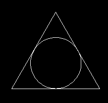
[edit | edit source]Draw equilateral triangle. And use menu item Draw - Circle - Tan, tan, tan to draw circle inscribed to triangle.
Draw equilateral triangle from lines:
Command: line
Specify first point: 200,200
Specify next point or [Undo]: @200,0
Specify next point or [Undo]: @200<120
Specify next point or [Close/Undo]: c
Object Snap - OSNAP Modes
[edit | edit source]Besides of using absolute and relative co-ordinates, you can use already existing points. Most used OSNAP points are:
Endpoint
[edit | edit source]Endpoint of an arc, elliptical arc, line, multiline, polyline segment, spline, region, or ray, or to the closest corner of a trace, solid, or 3D face.
Midpoint
[edit | edit source]Midpoint of an arc, ellipse, elliptical arc, line, multiline, polyline segment, region, solid, spline, or xline.
Center
[edit | edit source]Center of an arc, circle, ellipse, or elliptical arc.
Node
[edit | edit source]Snaps to a point object, dimension definition point, or dimension text origin.
Quadrant
[edit | edit source]Quadrant point of an arc, circle, ellipse, or elliptical arc.
Intersection
[edit | edit source]Intersection of two objects, an arc, circle, ellipse, elliptical arc, line, multiline, polyline, ray, region, spline, or xline.
Perpendicular
[edit | edit source]Point perpendicular to an arc, circle, ellipse, elliptical arc, line, multiline, polyline, ray, region, solid, spline, or xline.
Tangent
[edit | edit source]Tangent of an arc, circle, ellipse, elliptical arc, or spline.
Using Object Snaps
[edit | edit source]You can use object snap to specify exact co-ordinates, such as line first point or circle center. There are several ways how to do it:
- In the command line you can type first three characters. For example END for endpoint, CEN for center and so on.
- From the context menu. Hold the Shift key down on the keyboard and right-click the mouse to bring up the context menu.
- From toolbar menu.
- Using AutoSNAP. This mode can be switched on and off by key F3 or by click on button OSNAP on status bar. When mode is on, you will see hints during drawing. You can set AutoSNAP, right-click the mouse on OSNAP button and from context menu select Settings menu item. In complex drawing where there is more than one OSNAP point you can use TAB to cycle through all possibilities.
Practice OSNAP
[edit | edit source]Complete following tasks:
- Draw two lines. And then draw:
- Line connecting endpoints of these two lines.
- Line connecting midpoints of these two lines.
- Line from midpoint from first line and perpendicular to second one.
- Draw line and circle. And then draw:
- Line connecting circle center and line midpoint.
- Two lines starting in midpoint of the first line and tangential to circle
- Line perpendicular to first line and circle
- Concentric circle. (Use circle by center and radius)
- Connect endpoint of first line with 4 lines ending in circle quadrants.
- Connect two intersection by line.
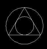
Draw equilateral triangle. And use circle by 3 points to draw inscribed circle (use OSNAP tangent) and circumcsribed circle (use OSNAP endpoint).
Conveyor belt scheme
[edit | edit source]Draw scheme of conveyor belt using commands circle, line and OSNAP mode tangent.
- Draw two circles:
- center 200,200 and radius 50
- center 400,200 and radius 70
- Connect circles with tangential lines (use OSNAP tangent)
Command: circle
Specify center point for circle or [3P/2P/Ttr (tan tan radius)]: 200,200
Specify radius of circle or [Diameter]: 50

Command: circle
Specify center point for circle or [3P/2P/Ttr (tan tan radius)]: 400,200
Specify radius of circle or [Diameter] <50.0000>: 70

Command: line
Specify first point: tan
Specify next point or [Undo]: tan
Specify next point or [Undo]:

Command: line
Specify first point: tan
Specify next point or [Undo]: tan
Specify next point or [Undo]:
Spur gear scheme
[edit | edit source]Draw scheme of spur gear using commands circle, line and OSNAP modes tangent and center. Known are center and radius (40 and 70 units) of two disks represented by circles. Because gear ratio is known, you know third circle radius (90 units), but without calculation you do not know center coordinates. Let AutoCAD find it, using circle constructed as tangent, tangent and radius. Use bottom parts of circles during tangent selection. Then connect centers of three circles by lines, representing supportive frame.
- Draw two circles:
- center 200,200 and radius 40
- center 400,300 and radius 70
- Draw third circle using Ttr (tan tan radius) option
- Connect circle centers with lines (use OSNAP center)
Command: circle
Specify center point for circle or [3P/2P/Ttr (tan tan radius)]: 200,200
Specify radius of circle or [Diameter]: 40

Command: circle
CIRCLE Specify center point for circle or [3P/2P/Ttr (tan tan radius)]: 400,300
Specify radius of circle or [Diameter] <40.0000>: 70

Command: circle
CIRCLE Specify center point for circle or [3P/2P/Ttr (tan tan radius)]: t
Specify point on object for first tangent of circle:
Specify point on object for second tangent of circle:
Specify radius of circle <70.0000>: 90

Command: line
Specify first point: cen
Specify next point or [Undo]: cen
Specify next point or [Undo]: cen
Specify next point or [Close/Undo]: c
- Back to CAD Course
- CAD Lesson Autocad Introduction Previous lesson


