Engineering Projects/Engineering Drawing

- See also Category:Graphical projections on Wikipedia
Engineering drawing is primarily used to provide information about an object rather than a pleasing image. It must convey enough information to create or use the object in the physical world.
Engineering drawings take many forms, and usually represent a three dimensional object. They tend to avoid color, instead using black lines only. Lines can be of varying styles and thickness to indicate outlines, dimensions, hidden detail, center lines, cross hatching and projections. Assembly drawings can show how a number of components can fit together, and it may take several drawings to fully describe a complex item such as a building, furnishing, design item, mechanism, or machine.
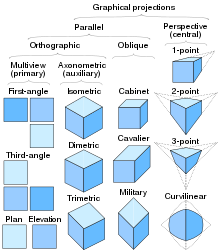
Broadly, technical drawings can be grouped as pictorial (less common) or orthographic. Pictorial drawing techniques provide a visual impression of what something looks like. These include:
- Isometric
- Planometric
- Oblique
- Perspective
[insert pictorial example(s)]
Orthographic drawings on the other hand present the information as a group of two dimensional representations. Each of these provides an outline and details looking from a particular direction. Orthographic drawings are like tracings of the outlines and key features of a photograph, and images are typically taken from three mutually perpendicular (orthogonal) directions. This translates conveniently into the physical world where someone needs to make or use the object. Where the object being described is complex, auxiliary views may also be provided showing the object from a suitable direction.
[insert engineering drawing example]
The actual views provided depend on the purpose of the drawing. Some special cases include house plans, which may only include a single view from the top to indicate the layout of rooms including walls, doors, windows and fixtures. A two dimensional sign might also only require a single view.
[insert building layout example]
(potential headings)
Angles of projection First Angle projection Third Angle projection Terms Lines Dimensions Scale Title blocks Sketches Physical drawings Computer Aided Design (CAD)