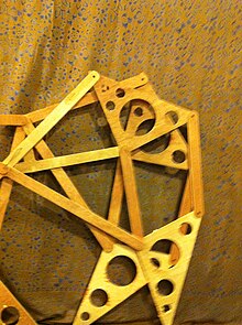
Engineering Projects/StrandBeest/Howard Community College/spring2012/p2550YFC/Legtutorial


StrandBeest:
[edit | edit source]Assembling the Legs in Preparation for the Drive Shaft
[edit | edit source]The purpose of this tutorial is to show how to assemble the machined parts into leg mechanisms and arrange them for assembly with the drive shaft.

Parts
[edit | edit source]- A - 2x Upper Leg or "Thigh"
- B - 2x Lower Leg or "Foot"
- C - 1x Center Mounting Bracket
- D - 4x Leg Connectors or "Knee Parts"
- E - 2x Upper Crank Connectors
- F - 2x Lower Crank Connectors
- Also used are 6 plastic grommet and pin connectors (see photo 3), 4 metal 1 1/4 inch 3/32 cotter pins(see photo 4) and a little bit of crazy glue.
Preparing the Triangles
[edit | edit source]- Part A, the thigh of the leg or upper triangle, will need to have 2 of the plastic grommets fitted in each. With the parts arranged as in the Parts Diagram above, one grommet is pressed firmly into the pre-drilled hole in the top point of each upper triangle and another in the outer points. You may need another small piece of wood to get it in. The fit is tight and secure without glue(Photo 5). The two inner points will be fixed to the frame later. Do not put grommets there.
- Part B, the lower triangle or foot, will get only one grommet per triangle. It will be placed on the outside point of each. The inside points will be fixed with long cotter pins later, no grommet needed. The bottom points are the toes and do not attach to anything, so no grommets there either.
Assembling the Legs
[edit | edit source]Now that the grommets have been placed, you can begin the assembly of the legs. First we attach the parts that use the plastic grommets.
- Put a small drop of Crazy Glue in each of the outer plastic grommets as in Photo 6.
- Take one Knee connector arm, Part D, and place a plastic pin in through the top hole as in Photo 7.
- Firmly press the pin trough the arm and into the glued grommet. The glue will lock the pin into the grommet and the arm will turn freely on the pin as in Photo 8.
- Place a second pin in the bottom hole of the arm. This one connects to the grommet on the outer top of part B, the Foot triangle.
- The last grommet/pin connection is the topmost point on the Thigh triangle. Put a drop of glue in this grommet as well.
- Use a pin to attach one end of an upper crank connector arm (part E). The other end will attach to the crank shaft.
- Place one Lower Crank Connector, Part F on top of a Knee connector, Part D and align the holes on one end.
- Place a Cotter Pin into the holes as in Photo 9.
- Insert the pin now through the inside point on the top edge of one of the Foot triangles, Part B, as in Photo 10.
- Bend out the ends of the Cotter Pin to hold parts securely together.
- Repeat this with the other leg in the pair.
This completes the 2 legs. You still need to attach them to the mounting bracket and crank.
Finishing Up
[edit | edit source]The 2 inner points of the Thigh triangles are now placed on the edges of the mounting bracket and aligned with the holes. The loose end of the inner Knee connectors, Part D are also connected here with a Cotter Pin through all 3 parts. This connection will be replaced by a single bar that runs through all leg assemblies.
In the Parts Diagram, you will see 2 short lengths not labeled with a letter. These represent the turning radius of the crank. You can attach one end of the crank radius to the center hole in the mounting bracket and the other end of the radius to the 4 loose ends of the Crank connectors from the legs. This will make 1 moving leg set, like in this video.
For this example, I took the one pre-assembled leg set shown in Photo 1 and attached it to the one I just built in the tutorial. I bent a coat hanger into the rough shape of the crank shaft. I have not included instructions for the coat hanger shaft because it is inferior and will not be used in the final StrandBeest. Here is a video of the 2 leg sets moving together. The motion is not very fluid due to the coat hanger crank shaft and the mounts not secured in place.
At least 4 more of these leg sets need to be put together. Once we have at least 6 of them, all that remains is to run a bar down each side, replacing all of the joints at the outer points on the mounting brackets and install the crank shaft.
