Power Generation/Hydro Power
Review: Lesson 2
The previous Lesson discussed the steam power station. Here are some points you need to remember from lesson 2.
- Schematic Arrangement of steam power station.
- Types of cooling sytems for a steam power station.
- Location & Efficiency of steam power station.
Preview: Lesson 3
This Lesson is about Hydro Power station. The student/User is expected to understand the following at the end of the lesson.
- Basics:
- Arrangements:
- Location:
- Pumped storage scheme:
Definition, advantages & disadvantages.
components that make up a steam power station.
Factors influencing selection of construction site.
Overview & comparison to Hydro-power station.

|
Figure 1:Krasnoyarsk hydroelectric station in Russia ( Click on image to view full size image ) |
Introduction: Hydro Power station
A hydro power station uses potential energy of water at high level for generating electrical energy.
This power station is generally located in hilly areas where dams can be built conveniently and large water reservoirs can be obtained. This kind of power station can be used to produce large amounts of electrical energy. In most countries these power stations are used as peak load power stations. This is because they can be started and stopped easily and fast.
Operation
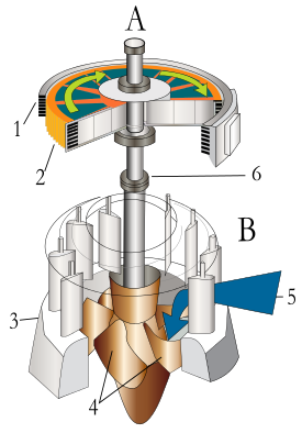
The water from the dam is lead to the water turbine through the penstock. Here the hydraulic energy of water is converted to rotational mechanical energy by the turbine. The turbine is connected to the generator through the turbine shaft and hence mechanical energy is converted into electrical energy by the generator.
Pros & Cons: what this power station presents
| Advantages | Disadvantages |
|---|---|
| Requires no fuel, thus called clean power station | Very high capital cost for dam construction |
| Small running charges and no need for specialised manpower | Uncertainty about availability of huge amounts of water |
| Simple construction & requires less maintenance | Skilled personel required for construction |
| Very robust & has long life | High cost of transmission line as plant is located in hilly areas. |
| Also used for flood control and irrigation | Impacts native watershed ecology |
Future generations will want to depend more on this type of electricity generating power station (and other renewable energy sources), due to a fast increasing depletion of fuels(Coal). There are a number of construction projects currently underway for this kind of power station around the world.
|
Hydo-electric power stations boast a simple design and construction method that is very robust and reliable(when done properly). The following sub topic discusses the most important constituents of this kind of power station (as shown in figures 2 & 3).
This schematic diagram must be properly understood. It is the basis upon which Hydro-electric power station designs are done. The individual power station complexity may differ slightly to the schematic and yet over and above that will use the same principle. | |||||||||
|
|
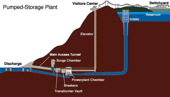
Pumped storage schemes are a convenient way of storing large quantities of energy which can be used during emergency or peaking times. Operation: During off-Peak hours, the plant draws electric energy from the electrical grid & uses that to pump water to the upper reservoir. When Peak time comes, the water from the upper reservoir is released & electric energy is generated in the lower reservoir. This cycle is repeated daily. By their nature, pumped storage schemes cannot be used as base load power stations. These are strictly used for peak time supply as they can be brought on-line quickly. Comparison:
| |||||||||
|
As evident from above table, both power stations are very desirable for use that goes outside of electrical energy generation confines. This schematic diagram must be properly understood. it is the basis upon which pumped-storage scheme power station designs are done. the individual power station complexity may differ slightly to the schematic and yet over and above that will use the same principle. | |||||||||
Below are equations used for calculations involving this kind of power station:
Weight of the water head:
(in Kg) ... Equation 3.1
The potential energy of the water head:
(in Joules) ... Equation 3.2
Thus the equivelent electrical energy will be:
(in kWh) ... Equation 3.3
Electrical enegry can also be expressed as:
(in kWh) ... Equation 3.4
Where:
- m = mass (in Kg)
- g = constant ≈
- h/H = water head height (metres)
- ρ = density of water ()
Below are furhter equations used for calculations involving this kind of power station:
Gross plant capacity (G.C):
(in Watts) ... Equation 3.5
The firm capacity (F.C) will therefore be:
(in Watts) ... Equation 3.6
Thus the yearly gross out put:
(in kWh) ... Equation 3.7
We can also estimate the volume of flow per annum:
(in kWh) ... Equation 3.8
Where:
- η = Efficiency
- m = mass (in Kg)
- g = constant ≈
- h/H = water head height (metres)
- ρ = density of water ()
it is imp part of the power plant
References
- This resource is prepared from Lecture notes by Thuvack.
- V.K Mehta & Rohit Mehta :- Principles of Power systems (1st ed.). S.CHAND .ISBN 81-219-2496-0


